you said the drive board is working fine, hope you tested it with the 7segment supplied by the kit maker.
if that part is right then what you are stuggling with, is to interface your large display.
5V may not excite enough voltage for the large display LEDs.
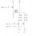
out puts A,B,...G , DP, DY1..DY4 are current sink, your buffer must be able to handle it,
if you have seriesly connected the LED in your display, then use a paropper voltage source only for the display and change all resistorsR1-R8 to limit the current (30mA), i beleive no need to use a buffer circuit, if i have understood it correctly.

")
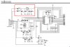
 , so what about using a photo coupler like K3010? the transistor output can be like a switch. DY1...3 and A,B... all can be wired to each photocoupler input. it can drive 20mA directly.