Continue to Site

Welcome to our site!

Electro Tech is an online community (with over 170,000 members) who enjoy talking about and building electronic circuits, projects and gadgets. To participate you need to register. Registration is free. Click here to register now.

  • Welcome to our site! Electro Tech is an online community (with over 170,000 members) who enjoy talking about and building electronic circuits, projects and gadgets. To participate you need to register. Registration is free. Click here to register now.

help with led sequencer

Status
Not open for further replies.
Hi Mazikowski,

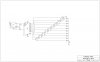
I know it's tempting to use the circuit with the CD4017
because it does it all in one box but if you want a led
bar it's getting rather complicated and you're gonna get
more trouble than you can handle.
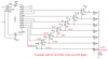
Stick to the circuit with the shift register, if you add
a second CD4015 you'll get 16 outputs.
And if you add transistors you can drive as many leds
as you want.

https://www.electro-tech-online.com/attachments/light-chaser-984-gif.13410/

on1aag.

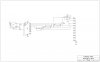
All I can really read on that diagram are the CD4015 and CD4093. Could you possibly clarify what other components you have listed on there?

Also, how would I limit it to only 10 LEDs (with the first on as long as the circuit is on)?

EDIT: Would I just leave 1 LED getting direct power (not on the shift register) and use 9 outputs with the 10th output going to the clear pin on all CD4015's?
 
Last edited:
Hi Mazikowski,

You need to add 1/2 CD4015 to the circuit and connect it
to the second half of the CD4015 the same way the second
half of the CD4015 is connected to the first half and move
the reset which is connected to Q1B to Q2C. That will give
you nine outputs, from 2 to 10.
The first "output" isn't really an output, the led with it's
series resistance is directly connected between Vcc and gnd
and will always stay lit.

You'll need only two CD4015's and one CD4093.

on1aag.
 
Mazikowski,
I forgot about the voltage drop on the diodes, sorry. I would suggest then to install the diodes in a staggered between each transistor. same amount of parts just a change in the schematic I am at work I will redraw it when I have time and repost it.
 
Mazikowski,
Here try this its has the same amout of parts the original had but allows for the voltage drop on the diodes.
 

Attachments

  • LED seq with led maintain.JPG
    LED seq with led maintain.JPG
    457.9 KB · Views: 595
Your circuit has too many diode voltage drops.
Emitter-followers don'r switch, they follow so when 10 LEDs are supposed to be lighted then the 10th gets 4.3V from its transistor, then each LED gets less voltage.
The 9th LED gets 3.6V, the 8th LED gets 2.9V, the 7th LED gets 2.2V and the 6th LED gets only 1.5V. LEDs 1 to 5 get less voltage.
The voltage to the LEDs is also reduced by the voltage across the 220 ohm resistor so this circuit won't work.

It might work a little better if the transistors were switches instead of followers.

So what if you took the diodes and put them between the bases on the transistors (like the first diagram, but on the other side from where they originally were)? I'm liking the shift register idea...
 
My circuit rases the voltage back up to 5 volts each time it switches the next transistor down the line so each LED gets 5 volts. voltage goes through the diode turns on the upper transistor the 5 volts gets dropped to about 4.3 volts but stills is enough to turn on the upper transistor.
 
Last edited:
Mazikowski,
Here try this its has the same amout of parts the original had but allows for the voltage drop on the diodes.
no it doesn't... voltage followers cannot "raise the voltage back up to five volts" as you claim in a later post.
 
Last edited:
My circuit rases the voltage back up to 5 volts each time it switches the next transistor down the line so each LED gets 5 volts. voltage goes through the diode turns on the upper transistor the 5 volts gets dropped to about 4.3 volts but stills is enough to turn on the upper transistor.

Dominus Vobiscum.

on1aag.
 
My circuit rases the voltage back up to 5 volts each time it switches the next transistor down the line so each LED gets 5 volts. voltage goes through the diode turns on the upper transistor the 5 volts gets dropped to about 4.3 volts but stills is enough to turn on the upper transistor.
No.
Your transistors do not switch because they are emitter-followers. The emitter voltage is 0.7V less than the base voltage.
Each diode reduces the base voltage of the next transistor by 0.7V.
With the 10th LED lighted then none of the other LEDs will light.
 

Attachments

  • LED sequencer.PNG
    LED sequencer.PNG
    34.8 KB · Views: 1,650
So would it work with the diodes between the bases on the transistors? This circuit is going to be powered by 12v, if that makes any difference.
 
So would it work with the diodes between the bases on the transistors? This circuit is going to be powered by 12v, if that makes any difference.

hi,
A shift register would be my choice, something like a 8bit 74LS164, its far easier to construct than all those diodes etc.:)
 
If I used 2 8bit shift registers as previously suggested, would I be able to use something like this:
**broken link removed**

where U1 is a CD4011 NAND gate. Only, instead of using the 4017 Decade Counter, use the 2 shift registers connected together...
 
I see audioguru I thought about that after I posted ...sorry. I studied it a little more and came up with this use a switch instead of a transistor and each time the voltage will be brought back up to 5 volts you could also use a optoisolator instead of the switch. I dont know what I was thinking about when I said use transistors..
 

Attachments

  • LED seq with led maintain.JPG
    LED seq with led maintain.JPG
    443.2 KB · Views: 566
Hi Ben,
I guess you didn't read the datasheet for a CD4066.
It switches signals, not currents for LEDs.
When its supply is only 5V then it is 470 ohms when it is turned on, then the LED is dim.
There is not enough voltage for any other LED to light.
 

Attachments

  • LED sequencer.PNG
    LED sequencer.PNG
    34.8 KB · Views: 871
audiogru i have used i to light a couple of LEDs before bt if it was needed to like as many as 10 like he wants then a ULN2803 to up the current to le LEDs.
 
If I used 2 8bit shift registers as previously suggested, would I be able to use something like this:
**broken link removed**

where U1 is a CD4011 NAND gate. Only, instead of using the 4017 Decade Counter, use the 2 shift registers connected together...
That works accept you want a resistor for each LED and the last output to the reset.
 
Then the last LED will never light.
The CD4017 counts to 10 then automatically returns to 1.
You forgot what he is trying to do: keep the lower lights lit until the cycle restarts.

he was also looking at two shift registers to do it, the single was just an example of the idea for commentary
 
Status
Not open for further replies.

Latest threads

New Articles From Microcontroller Tips

Back
Top