Continue to Site

Welcome to our site!

Electro Tech is an online community (with over 170,000 members) who enjoy talking about and building electronic circuits, projects and gadgets. To participate you need to register. Registration is free. Click here to register now.

  • Welcome to our site! Electro Tech is an online community (with over 170,000 members) who enjoy talking about and building electronic circuits, projects and gadgets. To participate you need to register. Registration is free. Click here to register now.

Help with Guitar Switcher/Preamp build

Status
Not open for further replies.

captainate

Member
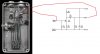
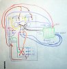
So I have built the Fulltone A/B switcher and love it. My bass player friend said he wants one with individual preamps on each channel. I have this in mind, but would like confirmation from this community that it'll work. I also need to have a volume attenuation control (not gain) in the circuit. What value of audio taper pot will I need and where in the circuit should it go? Thanks!
 

Attachments

  • AB_switcher.jpg
    AB_switcher.jpg
    146.7 KB · Views: 131
The best place for an attenuator would be on the output side; a 10K audio-taper pot should work fine. Connect the high side to the preamp output, the low side ground, and the wiper to the output.
 
A 10K pot would not attenuate below the noise floor like a 250K pot on a guitar, though, right? I don't need that but I'd like to improve my understanding of volume and resistance. I suppose since perceived volume is logarithmic, even 20 dB of reduction would be very significant. And with a smaller value of resistance, the fineness of the taper will dramatically improve, yes?

And to confirm, adding that preamp to the switcher wiring diagram looks ok?
 
Last edited:
The wiring diagram seems fine.

Since the guitar pickup has a much higher impedance than the output of this preamp, it would require a higher-value potentiometer to control. Generally speaking, the value of the pot resistance should roughly match the circuit impedance at that point.
 
So I built the pedal, and decided to add a feature not originally in the prototype. I put in a DPDT switch to choose between active and passive operation, so the switching functions and some attenuation through the potentiometers would still work if the guitarist forgot his 9V adapter.

I wired it up exactly like the diagram (sorry about the 3rd grade art project, I'm worthless with schematics) and I'm getting severe ground loop hum with both active/passive settings. Everything works great when there is no 9V connected and the switch is in the passive setting.

Obviously I want it to work in the active setting (as it did without the active/passive switch in prototyping), but ideally it should also work in the passive setting whether or not the power source is connected. Is there an easy way to do this?

I've also noticed that the way it's wired up right now has separate grounds for the switch circuit and preamp circuits. Should these all be connected to -9V? Thanks for your help!
 

Attachments

  • Diagram.jpg
    Diagram.jpg
    569.5 KB · Views: 186
Your "schematic" is very hard to follow, so I can't really tell, but it's likely you've created a ground loop there somewhere which would account for your hum.

All grounds (inputs and outputs) should be connected together, ideally at a single point ("star" connection), including the negative supply to the preamp (which I assume is at ground potential, correct?). Try that and see if it quiets things down.
 
Status
Not open for further replies.

Latest threads

Back
Top