Continue to Site

Welcome to our site!

Electro Tech is an online community (with over 170,000 members) who enjoy talking about and building electronic circuits, projects and gadgets. To participate you need to register. Registration is free. Click here to register now.

  • Welcome to our site! Electro Tech is an online community (with over 170,000 members) who enjoy talking about and building electronic circuits, projects and gadgets. To participate you need to register. Registration is free. Click here to register now.

Help with dynamic test load

Status
Not open for further replies.

imix500

Member
Hello all, new member on this forum.
Trying to build a simple adjustable dc load. Started with a published design and beefed up the power transistor stage.
I've been working on this project for over a year now on and off. It's been though about 4 revisions, but I haven't been able to make it behave.

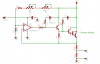
The most recent version uses a cmos opamp driving a common collector stage driving
the power transistor, a Powerex KS621K30 triple darlington rated at 300A. The problem is I shorted the module in the exact same way I shorted banks of smaller power mosfets. They all end up with about 6ohms in off state from E to C in both directions. Testing voltage was 24v at about 20A.
Here's the most recent as-built.
Thanks!
 

Attachments

  • Larger eLoad.png
    Larger eLoad.png
    16.4 KB · Views: 343
Last edited:
You need a very large heatsink to dissipate the 480W generated by the transistors. What heatsink are you using?
 
Last edited:
Hi crutschow, actually I need a bit over 1kW in dissipation capability with this load. This is the smaller of three units I have. The largest is water cooled, this one and the one in between are forced air cooled using large tunnel type sinks removed from some 100hp DC motor drives.
 
Here's an older version that used mosfets. If this would be the better way to go I could rebuild it without too much trouble.
 

Attachments

  • eLoad.jpg
    eLoad.jpg
    97.6 KB · Views: 311
I think this compensation method might give you more stability. You might have to fiddle with the R's and C's to optimize it. You can AC-couple a 100Hz square wave of a 100mV p-p or so into the + input of the op amp. Start with relatively low current. Look at the transient response at the top of your current sampling resistor using an oscilloscope. It doesn't need to have fast risetimes at that point, just little or no overshoot or ringing. This indicates that it is not likely to break into oscillation, which may be what killed your previous devices.
A similar technique should work on the Darlington-base circuit.
 

Attachments

  • eLoad comp.PNG
    eLoad comp.PNG
    90.8 KB · Views: 319
Hi Roff,
I saw that used in some commercial designs- I'll give it a try. I will start with one mosfet (I only have a couple good ones left) and see what the scope shows.
Let me ask you, I did notice before that even though the mosfets were from the same date code, the emitter resistors were dropping voltage within a pretty wide range. Is matching Vgs necessary here for paralleling mosfets like in class a amplifiers?
Thanks
 
Last edited:
Hi Roff,
I saw that used in some commercial designs- I'll give it a try. I will start with one mosfet (I only have a couple good ones left) and see what the scope shows.
Let me ask you, I did notice before that even though the mosfets were from the same date code, the emitter resistors were dropping voltage within a pretty wide range. Is matching Vgs necessary here for paralleling mosfets like in class a amplifiers?
Thanks
I don't have hands-on experience with MOSFET current sharing in a linear application, but I think matching is probably necessary. Not the best scenario.:(
 
That's what I figured. For matching I have a great little jig built from a Nelson Pass design for a "test everything" circuit which it truly is.
 
Last edited:
Ok, since the square wave output on my old generator doesn't work, I whipped up an astable at 100Hz. The duty cycle isn't great but I think it does the job. Attached is a photo of the gate of the 3055. This is with the new compensation components if it makes a difference. As you can see it isn't pretty. Any ideas?
 

Attachments

  • scope.jpg
    scope.jpg
    128.3 KB · Views: 228
Ok, since the square wave output on my old generator doesn't work, I whipped up an astable at 100Hz. The duty cycle isn't great but I think it does the job. Attached is a photo of the gate of the 3055. This is with the new compensation components if it makes a difference. As you can see it isn't pretty. Any ideas?
3055? You didn't have any 3055s in your schematics. Can you post a new schematic? Did you play around with the values in the compensation network?
 
Hey Ron, sorry the 3055 is in place of the TIP31. It went when the big powerex module went. The design will include a TIP31 when I get some in. I haven't played with the values yet. Should I start with higher or lower values?
 
Hey Ron, sorry the 3055 is in place of the TIP31. It went when the big powerex module went. The design will include a TIP31 when I get some in. I haven't played with the values yet. Should I start with higher or lower values?
I would try a lower excitation frequency. Below is a multivibrator that will give you roughly 50% duty cycle at about 7Hz. If it's too slow, make R1 smaller, or change it to a 1Meg pot with 10k in series.
I don't know which way to go on compensation. Probably make the cap bigger.:confused:
 

Attachments

  • 555 astable.PNG
    555 astable.PNG
    17 KB · Views: 274
Oh cool, I'll build that.
One more question before I leave you alone until I can get home and make changes. I am injecting the square wave at the junction of the 510 and 2k resistor at pin3 while leaving the pots and so the top section of the schematic still connected. Is that ok? I did try disconnecting the pots but leaving the 510 to ground and comparing the waveform and it didn't seem to do much to it. Thanks.
That's a good place to inject the signal. make sure it's coupled in through a BIG capacitor (1000 microfarads). My schematic has the polarity of the cap reversed. I'll fix it later. The + should be on the end that connects to the circuit you're testing. You only need a small AC signal there (added to the DC provided through the pots and the 2k resistor).. If your current sense resistor is 100 milliohms, 100mV p-p will give you a 1 amp p-p current on top of your DC current level. With 10 milliohms, you get an amp per 10mV p-p.
Don't disconnect the pots. They are what provides the DC voltage that is the reference for your current sense resistor. If you disconnect the pot, you get zero current. An AC signal superimposed on that would give you current for the positive portion of the cycle. Cutting the current off even farther on the negative portion of the input signal will still give you zero current during that time. The Idea is to set up a substantial current, and then modulate that by maybe 10% p-p with the AC input. A system that is not prone to oscillate should settle in a well-behaved manner, with little or no ringing, in response to a sudden change in the input voltage (provided by the AC-coupled square wave).
 
I took the common cathode stage out and am driving the mosfet through a 1k resistor. First off the weird thing. With both pots down it draws 2.1 amps at 5v. 100mV is appearing at the 2k resistor as expected, but 22mV after it at pin3. Should that resistor be dropping that much?

I built the multivibrator and it works great. The smallest output I can get is about 37mV and that turns the entire wave at the gate into a lower frequency wave. (terrible pic attached) If I increase the frequency, it settles down and the square wave can be seen cutting into the opamp's wave.

Also, I played with the compensation values and didn't really see much change. I went to a max of 1uF on the added cap and to 50k on the added resistor. The wave shape stayed the same.
 

Attachments

  • photo2.jpg
    photo2.jpg
    118.8 KB · Views: 272
Last edited:
That doesn't look like the 555 output. You should be seeing almost 50% duty cycle.
The op amp doesn't have a wave, as you said. That other crap is probably from ripple on your 12V power supply, or a result of poor grounding, or something like that.
 
Last edited:
That is at the gate of the mosfet. The wave shown in post 10 is what the output looks like without any modulation-thats what I meant by "the opamps wave". As input voltage/current draw increases, the whole waveform compresses and flattens out. When the square wave (which looks great) is added at low level, the waveform goes crazy.
I battled with the small switcher I'm using to run the whole thing, as well as the brushless fan's emi. I added a pi filter between the fan and added filter caps at the opamp board and it helped a lot. However I'm considering using a seperate supply for the opamp as I'm not convinced psrr is not still having an affect.
I'm using star grounding for the whole thing, but a ground problem is certainly possible.
 
I just noticed that the reference voltage (pin 3 on the op amp) is developed from the supply under test. This is wrong! It should be developed off +12V, which should be a linear regulator, and independent from the supply under test.
I think the best place to view the output waveform is across the sense resistor, although the gate waveform should be similar, but larger in amplitude. If you probe across the sense resistor, Make sure both probes are as close to body of the resistor as possible.
A star ground is essential. Does this include the connection of the 510Ω resistor to the sense resistor?
 
Oh, well that's a problem then. Funny, the first version of this actually used a precision 2.5v reference with the pots for the reference signal.
Since the supply is 12v on the money and wouldn't have any headroom for a 12v reg, could I use a 9v battery or 7809 to power the opamp and provide reference voltage to the pots? The only problem I can see with a battery is if I go back to a big power module, they need a good bit of drive current. More than a 9v could supply for too long.
Everything runs to the star ground except the fan and the power led. The 510ohm resistor literally ties directly to star gnd and pin3.
 
Status
Not open for further replies.

Latest threads

Back
Top