Hi, Let me start off that I know very little about how to design circuits, but am confident I will be able to put together a design if one is handed to me. The reason I'm posting here is I have a computer system I built for myself but I have found that the video card I am going to use (ATI AIW Radeon 9700pro) draws too many amps from my PSU on the auxillary power connector that the card uses when I press the power button. I have also discovered that if I can find a way to delay the ATI card from recieving power from its auxillary connector for just 1 second after I press the power button it will not trigger the overcurrent protection in my PSU and thus the computer will boot properly and run just fine. This is an issue that has been documented by many at various hardware enthusiast forums and alas we're good at building computer rigs, but few of us know that much about designing simple circuitry devices such as a Delay Relay.
So I hope that a kind soul here who happens to be good at this might be able to share with me a simple way to design a delay relay device that has a failsafe (so if an electronic part of it goes out it won't fry other expensive pieces of computer equipment) and takes input from 12V and 5V (the power that is sent through the 4-pin molex connectors on a computers PSU). I'm certain that given a design that will produces the desired delay of 1 second til power reaches the video card, I can have a working computer.
Thanks in advance for any help you might offer
---John
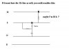
") . Im not sure how sensitive you power supply is because you might have a problem with this design due to delay times (mainly the relay). Ill test it some more tomorrow about the relay thing. If its is too long I can use a different design (not the normally closed contacts). I would prefer this design though because the relay is off except for that one second, I don’t like the idea of leaving the relay on the whole time the computer is on, plus if it fails somehow you are screwed. That’s why I like this design better. Based on the old monostable 555. The only other problem i could see is that the cap used to trigger it could not discharge fully, but this should really never be a problem since it discharges in about 5 seconds, just dont boot then shut down and reboot within 5 seconds.
. Im not sure how sensitive you power supply is because you might have a problem with this design due to delay times (mainly the relay). Ill test it some more tomorrow about the relay thing. If its is too long I can use a different design (not the normally closed contacts). I would prefer this design though because the relay is off except for that one second, I don’t like the idea of leaving the relay on the whole time the computer is on, plus if it fails somehow you are screwed. That’s why I like this design better. Based on the old monostable 555. The only other problem i could see is that the cap used to trigger it could not discharge fully, but this should really never be a problem since it discharges in about 5 seconds, just dont boot then shut down and reboot within 5 seconds.