Continue to Site

Welcome to our site!

Electro Tech is an online community (with over 170,000 members) who enjoy talking about and building electronic circuits, projects and gadgets. To participate you need to register. Registration is free. Click here to register now.

  • Welcome to our site! Electro Tech is an online community (with over 170,000 members) who enjoy talking about and building electronic circuits, projects and gadgets. To participate you need to register. Registration is free. Click here to register now.

Help with a Delay Relay circuit

Status
Not open for further replies.
Could someonre post a schematic that could work for my application, please.


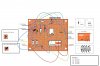
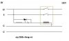
Ok, I need to build this circuit for my car alarm siren output. I can't figure out how to build it:
**broken link removed**

What I want the circuit to do:
  • I want it to pass the 12V+ signal once it has been received for 3 consecutive seconds
  • It should not pass the signal if it is received for less than 3 seconds
  • Once the signal stops, it should stop passing the signal and reset

Why?
I got some air horns because the alarm's siren wasn't loud enough. The alarm dosen't have a dedicated horn honk output. With the horns hooked up at all times the arm/disarm chirps also honk the horns and they're too loud for everyday use. I could disable the arm/disarm chirps but I like them.

With this circuit the siren will, if you guys can help, chirp by itself when arming/disarming the vehicle and the siren will blare continually when the alarm is triggered while the horns honk on and off, because of the flasher, after 3 seconds.

I'll use a standard automotive relay to supply the power to the horns so the circuit only need to supply enough current to switch the relay, not sure exactly how much that is.

Any help or suggestions are appreciated!

Thanks,
Gary
 
Hi Gary,

you have actually come up in someones thread.
Do a new thread,
i'm sure there are plenty people who would
do a relay circuit for you.

Cheers, John :)
 
John1 --I'm still holding out for the relay circuit to work, With regard to the SCR's and only taking .8 volts, I'm not so certain that wouldn't be a problem. This video card is pretty power hungry and 0.8 V is more than a 10% undercurrent from the 5V line. Under full load, I could probably expect to have 4.0~4.1V being fed to the video card at the time when it would require the most power too. My experiences with video cards particularly suggests to me that under full load, inadequate voltage can definately cause alot of instability. However, if it becomes apparent that there is no way I'm gonna get the relay to work, I'd probably try the SCR's in a last ditch effort.
-------------------------------------

Alrighty, I switched one of the 1N4001's around as it was facing the wrong way, and retested it, but it still flips the relay to the OC and and stays there. So I've come to the conclusion that I'm doing something wrong that isn't at all apparent to me (the newbie guy) but would probably be very easy to spot for one of you. So to hopefully make it really easy to troubleshoot, I'm posting this pretty close to scale model of my circuit I built. Let me know if you have questions or comments, and please please please let me know if you see my mistake.

All adjacent colored-in holes are to be considered sauldered
Yellow indicates 12V power, Red indicates 5V power, Black is ground of course. A Yellow wire carrys 12V power to some component, and a Blue wire is on its way back to the 12V ground. The wires in the picture are not at all drawn to scale, but hopefully they are easy to understand whats going where.

Man, I wish I had the skills to do this myself. I really want yall to know I appreciate all of your advice and help you've offered me.
 

Attachments

  • circuit_picture.JPG
    circuit_picture.JPG
    207.2 KB · Views: 594
Hi Cynet1,

I have tried to follow your layout,
but its too difficult panning backwards and forwards
and up and down, and following wires, im on 640/480
I got as far as trying to see if the relay contacts
were correctly wired, but i couldn't see how the pic
of the relay went to its pins.
Got the impression that the two 'makes' are on each
side. Coil at one end.

Maybe 'e' could see that its ok.

Dont worry, if you want to use a relay thats OK.
You just have to get the relay to close after a short
interval.

That really should not be a problem.

Back soon, John :)

(please press return after about 12 words, thanks)
 
got to do a virus check,
just had two unexpected shutdowns,
followed by blue scandisks.

Cheers, John :)
 
Oh,
Hehe, I see why it was tough to figure out the relay...
I forgot to draw a set of pins for the silly thing....

There we go, things should be much clearer now since I've updated with the correct drawing of the Relay.
 
Hi,

came up clean after an on line virus check.
must be just dodgy old 98se.

If you cant get to grips with that circuit,
you might like to consider something simpler.

I know you have gone to the trouble of building
that assembly, but sometimes simpler is easier.

You might like to consider this diagram.
Start with 10k and 20 MFDs and see what time
interval you get. Try altering the cap value
until you are happy with the interval.

Unless of course you've got it working!

Best of luck, John :)

(thanks for the shorter line lengths!)
 

Attachments

  • SCR-relay_timer.jpg
    SCR-relay_timer.jpg
    9.4 KB · Views: 572
ohh man that diagram is very hard to read, but im suprised at
how well it is at the same time. I really tried to figure it out, it looks
like the transistor (2n2222) is in wrong. Im having a hard time seeing
anything else... the top two legs of the metal case looks like they should
be switched, but im not too sure because it is hard to see... Do you have
a multimeter, or even an LED? If so test the output on pin 3 of the 555
timer, to see if it changes state at 1 sec, if so its something with the
transistor, if not its something before that. Does the transistor get hot at all? Make sure to check all solder joints carefully, If R1 or C1 is not
connected at both sides it could do that.
I do think the transistor is in wrong though, the leg you should have
going to R4 seems to be going to the relay(c), and the one going to the
relay should be going to R4(b), the third leg (e) looks fine.

If you have a multimeter/led/testlight/small 12v light.. hook one side to ground and the other side to Pin 3 of the timer, it should
turn on right as the power is turned on, and off 1 second later.
 
Hi,

Yes, i had a hard time following that layout.
I agree with 'e' that transistor is a likely candidate,
you can't really tell which wires are which.

Emitter should be to g,
Collector should be to the relay,
Base should be to the chip. (via the R )

Ive added a pic, just in case you're not sure.

(i hope i have the connections right,
if they chose to alter them,
they wouldn't ask me first, nor tell me after)

Cheers, John :)
 

Attachments

  • 2N2222.jpg
    2N2222.jpg
    16.8 KB · Views: 574
yea that picture shows the pins correctly, i think the TO-18 case
is kinda harder to follow than the TO-92
 
Thank you for the 2N2222 info
You were correct in identifying
my mistake there :roll: . The
electronics shop person drew me
a diagram of how that 2N2222
worked and what was what, but
he got it backwards :?

Anyway,
I was switched the 2N2222
connections and now when I
turn on power, the fan on the
other side recieves power.
However there is no delay.
I used another fan that has
these convienant lead wires
to test where power was
getting to. Whenever I did
anything that involved
Connection 2 on the LM555ch,
it does turn on the relay and
after 1 second the relay turns
off again. Obviously, whatever
my trigger event is supposed to
be to set off connector 2 on the 555
isn't triggering. Or maybe I'm
getting a bit ahead of myself trying
to pin down the cause. I wish I had
a multimeter, I do have one, its just
not here right now. Anyway, anytime
I touch R2 connection or R3
connection with the fan connectors
the Relay switches on and current
stops. Only thing I need to do now,
is get this to happen on initial powerup.

I'm sure this is getting old for yall,
but do you have any ideas what I
did wrong this time?

Just to make certain of one other thing
my resistors color coding and supposed
resistance are in the following just to
make sure I've got the right ones.

100Kohm Brown Black Yellow
10Kohm Brown black Orange
20Kohm Red Black Orange
4.7Kohm Yellow Purple Red

There isn't polarity on resistors
is there?
The resistors face like this:

12 Volt IN ---- 12Volt Out
R1 gold -------- brown
R2 gold -------- brown
R3 Red --------- gold
R4 Yellow -------- gold

Hopefully something I've said will
help identify what is keeping
that Trigger from triggering

Hmm. Now I'm wondering
about C1, on the 10uF device,
Is the Grey stripe supposed to
face the connection to the ground?
or the connection to the 12V line?

Presently it is facing the ground connection.
 
actually it seems like you found the problem, are you sure that R2, R3,
and C3 are hooked up correctly, R2 should be 10 Kilo Ohms, R3 should
be 20 Kilo Ohms, and C3 should be 10nF (.01 uF), if this is in correctly, (it
looks correct from that diagram), if it is how long are you waiting after
you turn it off to turn it back on, you need to wait at least 5 seconds or so
for C3 to drain, if it still doesnt work, try replacting C3 with a .1uF
(100nF) or if you have more 10nF caps put one or two parallel with C3.
Damn it worked for me. :cry:
 
Hey E and John1 I know its been awhile since
I posted here about the circuit. Truth be told
I never got it functional. But I now know
why. I talked with a Professor in the Electrical
Engineering Dept. at my University. He took a
look at the design you posted which he indicated
was viable in all regards except for the trigger
device. His analysis there (which he backed
up by printing the entire documentation of the
electrical properties/design/function of the LM555
IC chip) indicated that the LM555 requires a falling
waveform (ie low current) on the trigger circuit
to trigger the timer to countdown. I'm referencing
directly from the LM555 Timer design specs
available from National Semiconductor (February 2000)
which states "The circuit may be triggered and reset
on falling waveforms...". His suggested solution to
this was to add to the circuit design a 74/23 Monostable
multivibrator chip which would be able to switch that
high current being pulled by the 10nF and 20ohm
resistor to a low current for a split second if it was
placed between there and R2 thus causeing the trigger
on the LM555 to be triggered by the Falling Waveform
and then within 30 or so nanoseconds having the High
waveform resume which would start the LM555 timer
and allow everything to go as planned from there.
Of course I wasn't given a design or method for
designing this part of the circuit, but he gave me a
link or two to a circuit modelling program that I
could use to design a circuit on my computer without
having to build it and see if it worked. This particular
program is free to students and although isn't by any
means comprehensive, it should have the capability
of enabling me to redesign the circuit from R2 to the
trigger on the LM555 to make it function correctly.
I was hoping that if I got completely stumped, I
could still ask for your help on this, I have appreciated
your willingness to help thus far and the design you
gave me. Right now I'm going to try to incorporate the
extra IC chip into the design specs and see if the
program will show the circuit behaving properly. I
actually want to try my hand at this first cause I've
found that this is all very interesting to me. Really
I'm just posting this to let you know whats been
happening lately and what I've found out since our
last discussion. Thanks again for the
help you been thus far.
---John
 
Status
Not open for further replies.

Latest threads

New Articles From Microcontroller Tips

Back
Top