Electro Tech is an online community (with over 170,000 members) who enjoy talking about and building electronic circuits, projects and gadgets. To participate you need to register. Registration is free. Click here to register now.
Welcome to our site! Electro Tech is an online community (with over 170,000 members) who enjoy talking about and building electronic circuits, projects and gadgets. To participate you need to register. Registration is free. Click here to register now.
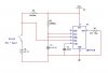
The bottoms of C1 and C2 do not appear to be connected to ground. Not sure what software you are using. There is no node on pin 1 ground connecting to rest of the circuit.
Output from pin 3 would also be connected to ground. Not sure why you have the output connected the way you have. If it is for feedback try connecting back to pin 7
I disagree with gjpollitt ,the output should not be connected to ground or tied back to pin7. The resistor from pin 3 to ground is okey as that is within the spec's of the 555. If the capacitor is really .68 Farad the timing is extremely long, 748,000 seconds. The output should be high for (t=1.1RC), once pin 2 is grounded.
I meant that looking at the way the circuit is drawn on the diagram i would assume the output is connected to ground. I didnt mean the output should be connected to ground as that is silly
This site uses cookies to help personalise content, tailor your experience and to keep you logged in if you register.
By continuing to use this site, you are consenting to our use of cookies.

")