Continue to Site

Welcome to our site!

Electro Tech is an online community (with over 170,000 members) who enjoy talking about and building electronic circuits, projects and gadgets. To participate you need to register. Registration is free. Click here to register now.

  • Welcome to our site! Electro Tech is an online community (with over 170,000 members) who enjoy talking about and building electronic circuits, projects and gadgets. To participate you need to register. Registration is free. Click here to register now.

Help with 555 timers for drag race lights

Status
Not open for further replies.

smithe30

New Member
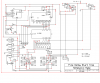
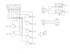
Ok so i have a "Christmas Tree" drag race light setup that consists of 4 incandescent, 12V lamps. The top 3 lamps are amber, and the one bottom green. Currently it is hooked up as seen in the picture. I know some about electronics, but I am still somewhat new to them. What i need is a circuit that will at the push of a button, turn on the top amber light, then turn the second amber light on .5 second later, then the next amber light .5 second later, and then the green light .5 second after that. When a light comes on the previous light should be off, and i would like the green light to stay on for 5 seconds, but if it is much simpler to have it only on for .5 second that is okay. I have read that this sort of thing can be done with 4 555 timers, 2 556 timers, or a 558 timer. I have several 555's and lots of resistors and capacitors available, so if i dont need to buy anything i would rather not. I would like the timer to run off the 12V DC battery if possible. Thanks alot for the help.
 
218-94176658.png
This is the image
 
I have a circuit that does exactly what you want. built it for a pinewood derby drag racing.
let me locate. be back soon
 
Here is schematic

need to revise as this has 24v solenoids that you won't need.
basic circuit is really quite simple but you need to be able to read schematics.
yes this circuit works.
 

Attachments

  • pinetree1.PNG
    pinetree1.PNG
    44.4 KB · Views: 2,215
  • pinetree2.PNG
    pinetree2.PNG
    30.7 KB · Views: 1,278
thank you, is there any way of doing this with only 555's? if no, its ok but i will have to order the other IC's of the internet. Thanks alot for the schematics, perfect.
 
Ok, so i made a slight revision removing the red lights, blue light, and solinoids. Is this what i need to make this work? thanks alot.**broken link removed**
 
You don't need the uln2804.
Will revise as simple transistors will do the same.
Transistor in lower left not needed as well.
 
Sorry for the stupidity, but is this what i want? The connection to Q0, is that left open? also what would you reccommend for transistors? do i need a diode across the relay coil? thanks alot.
251-ghkghjvky.jpg
 
Last edited:
do not run without some base resistors
you would be better off running the electronics on 5 volts as the relays are cheaper under $5 each.
the 4017 will not output more than 25ma I recall.
a 5 volt sensitive relay = 16ma with contacts rated at 3amps.
you may have to reverse the light sequence. put bulbs in and test. suggest using LEDs for testing just connect to transistor collectors or leave relays unconnected and use leds instead. then install relays.
but you need base resistors IMO.
also a decoupling cap on pin 5 to ground and 8 to ground.
will try and get some drawings for you later
 
Thanks alot, the reason i wanted to use these relays are because i have lots of them, and i also have lots of 2N3904 ans 2N3906 transistors, but if it is much simpler to run with 5v relays i will go that route. Thanks alot.
 
Q0 doesn't need to be connected; it's just an unused output.

Your circuit is fine with 12V relays, if you already have the parts. Just put a resistor (something between 470 and 1K is good) in series with the base of each transistor. Yes you need a diode across each relay coil.
 
2N3904 are the transistors, and the relays are the 12v bosch ones. What can i use for simple diodes, and are these diodes in the right direction? also these decoupling caps, how exactly do those fit in? Thanks alot.
290-revision2.png
 
what is the coil resistance on the relays?
this has a bearing on the base resistor resistance value.
a good reference to start is a 10 to one ratio.
coil = 100 ohms, base resistor = 1k
 
The coil resistance is ~75 ohms, so i should use rougly a 750ohm resistor? Are 2N3904 transistors suitable here?
 
the 2n3904 is only good for 200ma. at 12v and 75 ohms your pulling 160ma already
most any NPN with a to-220 package should handle the 160ma
Bipolar Transistors
get transistors that will handle at least 300ma. more is better IMO.
of coarse you could go to mosfets and forget the relays??
 
Status
Not open for further replies.

Latest threads

New Articles From Microcontroller Tips

Back
Top