Continue to Site

Welcome to our site!

Electro Tech is an online community (with over 170,000 members) who enjoy talking about and building electronic circuits, projects and gadgets. To participate you need to register. Registration is free. Click here to register now.

  • Welcome to our site! Electro Tech is an online community (with over 170,000 members) who enjoy talking about and building electronic circuits, projects and gadgets. To participate you need to register. Registration is free. Click here to register now.

Help understand circuit

Status
Not open for further replies.

ffp

New Member
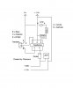
I found this homemade prank shocker with this circuitry and i'm trying to understand how it works.

shocker.jpg

What is the resistors for? I think the transistor is there to work as a switch to make a variation in current and make the transformer work, but how does it do that? and the capacitor, what's for?
 

Attachments

  • shocker.jpg
    shocker.jpg
    38.7 KB · Views: 449
The resistor limits the current through the LED to a suitable value (a few mA). The transistor is indeed a switch, controlled by the voltage generated by the smaller winding on the transformer. The cap stores charge to build up a high voltage from the individual pulses generated by the larger transformer winding.
 
Thanks for answering. But how will a current flow through the transistor base, to close the transistor switch, since the switch is open from the start? How does the transistor works in this circuit?

Also, what would be the difference in the output without the capacitor? Wouldn't the voltage be the same?
 
The circuit redrawn should make it easier to understand its working.

The transistor base gets its drive thru the 220 Ω resistor.
The increase in collector current drives the transistor even more thru' the transformer action and continues till the transistor saturates.

At the same time, the voltage at the other end of the transformer is -ve, the diode conducts and charges the 22 πF capacitor with a negative potential.

Once the transistor saturates, the base drive due to transformer action reduces, reducing the collector current and so on till the transistor cuts off.

The process starts all over again.

The grounding of the 22 πF capacitor can be to 0 V instead of +1.5 V; the diode can be reversed for a +ve High Voltage instead of -ve., unless there is some other reason.

Ramesh
 

Attachments

  • Ckt.jpg
    Ckt.jpg
    11.2 KB · Views: 336
Let me see if i got it. Initially the current will not flow through the primary windings, because the swith is open. But it will flow through both secondaries windings resulting in chargin the capacitor (or maybe not at this voltage, depending on the capacitor) and going through the 220 resistor that flows to the transistor base. Once the base have current, the switch will close and now there's current flowing through the primary coil, wich now induces a higher voltage in secondary coils wich charges the capacitor.
And the switch will open and close according to transistor saturation, creating the variation in voltage necessary to make the transformer work.

But i still have a few questions:

- Why does the transistor saturates?
-And could be a 4 pin transformer? Instead of smaller windings go to transistor base, could it go directly from 220 resistor to transistor base?
 
The transistor (switch) saturates (turns on) because the base current from the 220 ohm resistor is sufficient to saturate it. The transistor turns off because the voltage induced in the small secondary winding when the transistor turns on is opposite polarity to the base current from the 220 ohm resistor, cutting off the base current. That is why the base current is made to flow through that smaller secondary winding. Otherwise the transistor would alway stay turned-on.
 
Last edited:
It should simulate OK. Pay particular attention to getting the transformer and its connections correct. Use coupled inductors for the transformer so you have control over the inductance of the individual windings. Use, say, 0.2 mH for the primary, 0.1 mH for the transistor base winding, and 60 mH for the main, secondary winding to start with. Connect the transformer so that the phasing dot of the primary is opposite to the phasing dots of the two secondary windings, referenced to ground.

Getting the transistor to work without failing in the real world could be a problem, as I see it, since the voltage spikes could be very high. The saving grace might be that the spikes are so short in duration they might not actually cause damage (at least maybe not immediately).
 
Last edited:
Can this circuit be done with a 6pin transformer? I got one from a AC/DC phone charger that have 4 pins in high voltage and 2 pins in low voltage. Would it be the same except for 1 pin that would remain unconnected?
And what's the transformer relation to get the 450V output?
 
It might work with the 6-pin transformer. The '2 pins in low voltage' could be used for the transistor base drive. Of the other pins, the 2 with the highest resistance between them would likely be best for the main output winding.
 
Try replacing the 220Ω resistor with two 500Ω in series (making a total of 1kΩ).
 
Well, i have a 1k resistor and tryed before, but i could try again. I thought a higher resistor would be less effective than one closer to 220Ω. Now i'm using only one 500Ω and i'm getting 1.5V...

Also, in the link i posted, doesn't the circuit posted differs from what he did?
 
Also, in the link i posted, doesn't the circuit posted differs from what he did?

No, not that I can see. Does your transformer look exactly like the picture of the transformer posted in the link you posted?
 
Yes it is the same 5 pin transformer. The pins are 1,2,3 for the 3 pins windings and 4,5 for the two pins windings while in the image the pins are 1,2 for the two pins windings and 3,4,5 for the 4 pins. So, should the transistor base be soldered into the first pin from the left of the 2 pins side, like the guy did, or into the first pin in the 3 pin side, like the image with electric components symbols? Got it?

I'll see if the transistor and diode are working, but i don't know how to see if the transformer is...

I'm not sure I understand. Are you saying the pins have numbers next to them on your transformer? If so, I would disregard them and wire your circuit like the photos show. In the photo of the upside-down transformer, the upper two pins on the left side are the primary winding terminals (That is also evident from the heavier wire on those pins). The upper pin on the right side is supposedly the tap on the secondary winding (though I can't see the end of the tap wire soldered to the pin like I can see on the other pins --maybe it's hidden by the pin). The bottom pin on the leftmost side is one end of the secondary winding, and the bottom pin one the right is the other end of the secondary winding. You can use an ohmmeter to see which end of the secondary winding the tap is closest to, as a check (more turns=higher resistance on the ohmmeter). You can also use an ohmmeter to check that the primary terminals (upper two pins toward the left) are not connected to any of the other pins.

Once it is all connected, if it still doesn't work try swapping the connections to the pins of the primary winding.
 
Last edited:
No, there's no numbers nexto to the pins. All i was saying was in the two pictures i posted in my first post, one is the circuit schematics and the other one is the "real" components connected. The two images have different pins number and therefore different connections of the elements.
For example: the transistor base is connected to one of the three pins in the schematics, while in the components image, the transistor base is connected to one of the two pins.

BUT, considering that what the guy showed in his photos is the right circuit, mine still doesn't works. I'm getting ~1V output even without resistors (tryied with an open circuit).
 
No, there's no numbers nexto to the pins. All i was saying was in the two pictures i posted in my first post, one is the circuit schematics and the other one is the "real" components connected. The two images have different pins number and therefore different connections of the elements.
For example: the transistor base is connected to one of the three pins in the schematics, while in the components image, the transistor base is connected to one of the two pins.

The pins numbers and connections in the two pictures do match, however. Three pins located externally (physically) on one side the transformer does not necessarily mean that they are all associated with the same winding inside the transformer. Trust the schematic and try to determine which pins on your particular transformer match the schematic, using an ohmmeter. The size of the wire of a particular winding soldered to the pins on the transformer is the same at each end of that winding, however, and that offers a clue. The secondary winding from one end to the other end will have a higher resistance than the primary winding because it has more turns and thinner wire.

BUT, considering that what the guy showed in his photos is the right circuit, mine still doesn't works. I'm getting ~1V output even without resistors (tryied with an open circuit).

The phasing of the windings could be different from that guy's transformer, even if everything else looks the same and ohmmeter checks, and visual check of the wire size of the windings, verify correct transformer connections. If that all check out, try swapping the connections to the primary winding terminals of the transformer (indicated as pins 1 and 2 in the schematic.) if ohmmeter checks verify the transformer connections.
 
Last edited:
With only a 1.5V battery, what lights the LED? Most LEDs have a Vf > 1.5V???
 
With only a 1.5V battery, what lights the LED? Most LEDs have a Vf > 1.5V???

Probably the average of all the spikes/ringing generated, but I would try to get the circuit working without the LED since it is not needed anyway.
 
Status
Not open for further replies.

New Articles From Microcontroller Tips

Back
Top