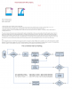
Friend here by doing very hard work I have made a circuit which I have attached in my attachment..
And the working of this circuit are as follows :
=============================================================================
We will start the sequence with the tank FULL - and the timer PAUSED
Twist the EMPTY wires together - but keep the FULL and the WATER wires separated - as in the drawing.
Turn on the power.
The green LED should be lighting - and the other two LEDs should be off.
THE Control IC (Ic2)
Pins 1 & 2 should be low
Pin 3 should be high.
The green LED should be lighting
Pins 5 & 6 should be high
Pin 4 should be Low.
The red LED should be off
Pins 12 & 13 should be high
Pin 11 should be low.
Pin 11 should hold pin 1 of the timer IC low.
And the timer should be PAUSED
With the yellow LED off
Pins 8 & 9 of Ic2 should be high
Pin 10 should be Low.
And the blue LED should be off.
Separate the EMPTY wires - to simulate an empty tank.
Pins 8 & 9 of Ic1 should go high
And pin 10 should go low.
Pin 10 should take pins 5 & 6 of Ic2 low - through D5
Pin 4 should go high
And the red LED should light.
Pins 1 & 2 of Ic2 should go high.
Pin 3 should go low -
And the green LED should switch off.
Pins 12 & 13 should go low
Pin 11 should go high
Pin 11 should take pin 1 of Ic1 high
And the timer should start to run.
Wait a while - to confirm it's running properly.
Pins 8 & 9 of Ic2 should still be high
Pin 10 should still be low
And the blue LED should still be off.
REMEMBER THAT THE TANK CANNOT BE FULL AND EMPTY AT THE SAME TIME.
ALWAYS - start by reconnecting the EMPTY wires -
To simulate the tank BEGINNING to fill.
Pins 8 & 9 of Ic1 should go low.
And pin 10 should go high.
The tank is now FILLING - But not yet full.
So the red LED should continue to light
The green LED should remain off.
And the timer should continue to run
Wait a while - to confirm it's still running properly.
NEXT
Touch the FULL wires together BRIEFLY.
Pins 1 & 2 of Ic2 should go low
Pin 3 should go high
And the Green LED should light
Pins 5 & 6 should go high
Pin 4 should go low
And the red LED should switch off.
Pins 12 & 13 should go high
And pin 11 should go low.
Pin 11 should take pin 1 of Ic1 low
And the timer should PAUSE -
With the yellow LED off.
Pins 8 & 9 of Ic2 should still be high
Pin 10 should still be low
And the blue LED should still be off.
THIS TAKES US BACK TO WHERE WE STARTED.
==============================================================================
But the problem is ....
When the EMPTY (or LOW) sensor opens - it enables the timer output.
If - at that time - the timer is in the ON phase - the pump will start straight away.
And - if the timer is in the OFF phase - the pump will start WITHIN 30 minutes.
The timer is powering-up at the beginning of the OFF phase
So the pump will begin to run after 30 minutes.
And I want That It should to start the pump immediately - without the previous delay.
and after starting the pump it should check the availability of water for 10 minutes and if water doesn't comes
then it will turn off the pump and restart after 30 minutes... and this repeats untill the tank becomes full..
========
As the water comes , water sensor will detect the water and pause the timer and the pump will continue to run..
but the second problem.... is ... if the water supply goes in between before the tank is full, the pump will keep on running..
I want If the water is available ,start the pump(As my circuit does) but as the water goes it will not turn off the pump but it will wait for 10 minutes and check the availability of water(If water comes then it will pause the timer and the pump will continue to run) else it will turn off the motor and restart after 30 minutes.. and this repeats until the tank becomes full...
===
Thanks in advance...
")