Continue to Site

Welcome to our site!

Electro Tech is an online community (with over 170,000 members) who enjoy talking about and building electronic circuits, projects and gadgets. To participate you need to register. Registration is free. Click here to register now.

  • Welcome to our site! Electro Tech is an online community (with over 170,000 members) who enjoy talking about and building electronic circuits, projects and gadgets. To participate you need to register. Registration is free. Click here to register now.

Help required to complete ???

Status
Not open for further replies.
That should do the trick. The 'on' signal from the 3hr timer is now effectively 'ANDed' with the 10 min 'on' signal from your (unnecessary:)) 10/30 timer.
 
He is using a NC relay with the 3hr timer circuit. Wouldn't you have to invert the signal first using a NOT gate and then AND both the signals?
 

Attachments

  • Capture.PNG
    Capture.PNG
    10.5 KB · Views: 137
Last edited:
Hi... abchopra ji... I have attached complete description of my relay... and As well as I have posted your circuit diagram...

So please have a look...

thanks :)
 

Attachments

  • relay.jpg
    relay.jpg
    280.7 KB · Views: 119
Last edited:
Using an NC relay means that if the relay is not energised for 3 hrs it will be energised for 21 hrs per day. That's wasting power. Personally I'd do away with relays altogether and use an opto-isolator driving a triac to switch the pump on/off.
 
He is using a NC relay with the 3hr timer circuit. Wouldn't you have to invert the signal first using a NOT gate and then AND both the signals?

I considered this in the modification i posted in #60. i reduced one gate by using one of the existing NAND.
 
Im sorry! I mistakenly put a NAND gate instead of AND

I think you should use mbarazeen solution. As i couldnt go through your whole circuit and just see how the relays were working.
 
Last edited:
Hi... mbarazeen.. !!

Thanks for your circuit diagram ... but can you explain it...
Because I am little bit confused..

So please elaborate.. your circuit diagram...

:) :) :)
 
Last edited:
see the attached diagram, i have marked the existing out puts as A and B
A is out put from final NAND gate from 3hr timer in your circuit
B is 10min timer out put

the condition you need for the pump to rum is A=0 and B=1
so the final output is = A'.B as shown in the attached diagram.

if you are not familiar in Boolean algebra just have some reference it will help you a lot to understand.
 

Attachments

  • removing a relay.JPG
    removing a relay.JPG
    106.8 KB · Views: 127
Thanks ... mbarazeen....

I will require some time to analyze your circuit....
I am busy in analyzing your circuit...
I will reply you back as I am done...

... thanks again...

:)
 
Hi.... mbarazeen ..
I have deeply look at your circuit but I am sorry...

I think you need to reconsider the logic.

As it stands as per your circuit - the motor will only run while the 3-hour timer is not running

i.e. while pin 12 of the 4060 is being held high.

The moment the 3-hour timer starts to run -

pin 12 (A) will be taken low - and the relay will de-energize.
=============

Friend what I want I have told you previously .. and gaven lots of information about my project...

Here the 3hr timer is the total time in which all the operation will perform like turning on/off motor according to the logic's..
but the problem is not in logic... logic is good working...

Here The total time period will be 3hr and after 3hr the motor pump will stay off... untill the 3hr timer starts...

So the all the process of turning motor on/off will be done in between 3 hr.. because after 3hr motor will remain off.... untill the 3hr timer starts again..

But friend I have used my mind and created a circuit diagram which I have attached in my attachment.. and the details I haved gaven below...
so please have a look...

=================================================================
=======================================
First.....

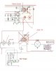
AS THE 3HR TIMER WILL BE RUNNING IT'S PIN 12 & 13 WILL BE LOW AND OUTPUT PIN 11 WILL BE HIGH..
AND OUTPUT PIN 11 WILL WILL ALSO TAKE PIN 6 OF GATE2 & PIN 8 & 9 OF GATE 3 HIGH...

SO THE OUTPUT OF GATE 3(PIN 10) WILL BE LOW AND TIMER WILL BE RUNNING...
TAKING IT FIRST ROUND OF 10 MINUTES ON ....
IT WILL TAKE PIN 1 & 2 OF GATE 1 HIGH AND THEREFORE THE OUTPUT AT PIN 3 WILL BE LOW..
PIN 3 WILL ALSO TAKE PIN 5 OF GATE 2 LOW..

THEN..
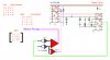
NOW WHAT WILL BE THE OUTPUT OF GATE 2(WHICH IS USED TO TURN MOTOR ON/OFF)..

TO DRIVE MOTOR WE WANT 5 & 6 OF GATE 2 LOW, SO THAT OUTPUT PIN 4 BECOMES HIGH TO DRIVE MOTOR..OR
0 + 0 = 1
1 + 0 = 1
0 + 1 = 1
=====

SO WHAT RESULT WE GOT HERE...
AS 3HR TIMER IS RUNNING SO PIN 11 IS HIGH WHICH ALSO TAKES PIN 6 HIGH.
AS ANOTHER TIMER IS TAKING IT'S FIRST 10 MINUTES ROUND , SO PIN 3 IS LOW..

1 + 0 = 1


SO THE INPUT OF GATE2 PIN 5 & 6 BECOMES LOW THE OUTPUT OF GATE2(PIN 4) IS HIGH AND WILL TURN ON THE MOTOR.

NEXT.....
3 HR TIMER IS RUNNING....

TIMER 2 BECOMES OFF AFTER 10 MINUTES AND IT WILL STAY OFF FOR 30 MINUTES .. AND WE WANT TO TURN OFF
THE MOTOR... SO WE WANT..

1 + 1 = 0.


SO WHAT RESULT WE GOT HERE...

AS 3HR TIMER IS RUNNING SO PIN 11 IS HIGH WHICH ALSO TAKES PIN 6 HIGH.
AS TIMER 2 WILL REMAIN OFF TILL 30 MINUTES , SO PIN 1 & 2 IS LOW AND PIN 3 IS HIGH..

1 + 1 = 0


SO THE INPUT OF GATE2 PIN 5 & 6 BECOMES HIGH AND OUTPUT OF GATE2(PIN 4) IS LOW AND IT WILL TURN OFF THE MOTOR.


LAST....
3 HR TIME IS OVER AND NOW 3HR TIMER IS OFF...

WE WANT TO TURN OFF THE MOTOR...
SO WE WILL DO THIS BY PAUSING THE TIMER2.


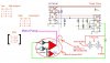
AS 3HR TIMER IS OFF , ITS 12 & 13 PIN WILL BE HIGH AND OUTPUT PIN 11 WILL BE LOW..
GATE3 INPUT PIN 8 & 9 TO BECOME LOW.. AS IT BECOMES LOW THE OUPUT PIN 10 BECOMES HIGH AND IT WILL
TAKE PIN 12 & 13 OF CONTROL CIRCUIT TO HIGH AND THE OUTPUT PIN 11 OF CONTROL CIRCUIT BECOMES LOW..
WHICH WILL TAKE PIN 1 OF TIMER2 LOW.. SO THE TIMER2 WILL PAUSE..

AND THE MOTOR PUMP WILL BE OFF..
AND THIS REPEATS...
AS THE 3HR TIMER STARTS TO RUN...

===========================================================

Thanks for co-operation....
Thanks in advance.. :)
Yusuf..
 

Attachments

  • Removing_relay.jpg
    Removing_relay.jpg
    158.5 KB · Views: 123
Hi.... mbarazeen ..
I have deeply look at your circuit but I am sorry...

I think you need to reconsider the logic.

As it stands as per your circuit - the motor will only run while the 3-hour timer is not running


Yusuf..

i have not done any modification other than changed the relay logic to semiconductor logic...i noticed you use Boolean logic wrongly, for AND gates 1.1=1, 1.0=0, 0.0=0 similarly OR gates will be 1+1=1, 1+0=1, 0+0=0...., Since you use NAND gates you have to make correct expressions.

you just experiment what i have posted. if it really needs to work other way you can insert an inverter before you give 3hr timer input..
 
I have tested your circuit but id doesn't work as I want..
I have given above the circuit with information....
please have a look... and reply...

thanks :)

and are you Muslim...
 
you circuit is not connected as i suggested...then how to get desired out put? see the attachment. may be you are not clear about basic logic gates.

for personnel questions its not a good place, you could rather send me a private message...

razeen
 

Attachments

  • connection to pump.JPG
    connection to pump.JPG
    104.7 KB · Views: 134
I have tested your circuit as you have given and I got the following result :

If the timer is running , pin 13 will be high and as the second timer
is running for 10 minutes so the pin 12 will also be high..

and the output of 11 will be low which also takes pin 12 and 13 low...
and the output at pin 11 will be high...
so motor pump will start....

this is ok.......

and as the second timer becomes off for 30 minutes....
so the pin 12 will be low and as the 3hr timer is running the
pin 13 will also be low in which the output at pin 11 will be
high , which also takes pin 12 & 13 high and the output at pin 11
will be low.....

and the pump will turn off...

This is also ok...
As I deserve...

But please look below where the fault exists...

After 3hr pin 13 will be high....
And the second timer will be keep on running untill the tank becomes
full or water exists...

So here the another timer is running and it's work is to be on for
10 minutes and stay off for 30 minutes...

So, as the 3hr timer is off it will take pin 13 to high..
And according to the condition of another timer...
If it is on (10 minutes) it will take the pin 12 to high.. in which
both pin 12 & 13 will be high so the output at pin 11 is low..
which also takes pin 12 & 13 low... and the output is high..
so the motor will turn on......

This is the problem...
We want as the 3hr timer becomes off it should turn off the motor..

This is done if the another timer is off(30 minutes)..
SO the pin 12 will be low and as the 3hr timer is also off so
pin 13 will be high .. and output at pin 11 will be high..
in which it will take pin 12 & 13 to high and the output at 11 will
become low... and the motor will turn off.

===================
But we want :
The condition doesn't matter of another timer(10 on /30 off).
If should turn off the motor if the another timer is on(10 minutes) or off(30 minutes)..

As the 3hr timer becomes off it should turn off the motor....

This is a problem...

and I have tested your circuit previously.. but the result was same
as I mentioned above..

And the second circuit I have created and I have also given the
information at post #72...


So please have a look..

The gate1 , gate2 & gate3 in the circuit diagram is an another cd4093 IC.. gates
which I have used...
And the pin 12,13 & 11 is the 4060(3hr timer) gate...


Thanks for co-operation...
Waiting for help ??

Yusuf..
:)
 
could you get it working with relays??? as in your post #48, actually its your circuit not mine..i just modified to remove two relays by implementing logic gates.
 
could you get it working with relays??? as in your post #48,
Yaa it is working with relay ... very well..

actually its your circuit not mine..i just modified to remove two relays by implementing logic gates.
Yaa I know friend...

So friend what will be the solution of this... :)
 
Yaa it is working with relay ... very well..

if it was working with relay, definitely it has to work with my modification, i beleive you are making a mistake some where in the connection...no way to help without looking in to the PCB you have made..
 
Status
Not open for further replies.

Latest threads

Back
Top