Continue to Site

Welcome to our site!

Electro Tech is an online community (with over 170,000 members) who enjoy talking about and building electronic circuits, projects and gadgets. To participate you need to register. Registration is free. Click here to register now.

  • Welcome to our site! Electro Tech is an online community (with over 170,000 members) who enjoy talking about and building electronic circuits, projects and gadgets. To participate you need to register. Registration is free. Click here to register now.

Help needed on driver circuit for bi-colour LED

Status
Not open for further replies.

vielle568

Member
Hello,

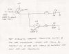
I'm trying to add a bi-colour LEDs to my project to act as an indicator. It will show green when the circuit is powered up and then turn red when a certain signal is sent. Vcc is at 5 volts and the 'signal' mentioned previously is tagged and sent to the base of a BC558C transistor to switch on the red half of the LED. This part works OK, but how do I invert the circuit to turn off the green part of the LED? I'm sure it's simple but I'm not an EE and I can't figure it out. I've tried various combinations of transistors (both PNP and NPN) but without success.

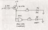
I've now got a flip-flop wired in place, but the LEDs switch only on the leading edge of the signal pulse and do not return when the pulse ends. Can the 4013 be wired to follow the signal pulse both leading and trailing edge?
Any suggestions welcome. Thank you.

Vielle568
 
Last edited:
It depends on the LED: does it have two legs or three?

Please post a schematic.

If it's a two leaded LED, it needs to be connected between two logic outputs. Suppose the red anode is connected to A and the green anode is connected to B. If A is high and B is low it will be red, if B is high and A is low it will be green and if both A and B are the same the LED will be off.
 
Last edited:
Hello Again,
The bi-colour LED I am planning to use has three legs; the central one is the common cathode and the outer legs are the red and green anodes.
I've attached part of my schematic so you can see what I'm trying to do. There's already one LED in the circuit; I'd prefer to make it a bi-colour LED so I can use it to show when the power's on as well as warning signal.
Again, any help greatly appreciated.
Vielle568
 

Attachments

  • schema1.pdf
    453.2 KB · Views: 801
It's just tow LEDs in the package.

Simply connect a logic inverter with the output going to the green LED and its input to the red LED. When the power is on the green LED is illuminated, if a signal turns on the red LED the green LED goes out leaving the red LED lighted.

Your schematic angles at 90° was difficult to read so I rotated it and converted it to a .jpg.

The transistor should also be NPN, not PNP, I've corrected it for you.
 

Attachments

  • schema1 bicolour.JPG
    schema1 bicolour.JPG
    170.6 KB · Views: 1,792
Bi-colour LED

The transistor was a PNP because the IC output (pin 5) dropped to ground when the input frequency went above the reference. This arrangement worked OK to light the LED when the frequency was high. I think it'll be the inverse if I change to a NPN transistor.

I did try putting a not gate in the circuit. It wasn't an IC but just a simple transistor circuit used to invert the signal, however something wasn't right and it didn't work; the LED was on all the time. I'll try your suggestion and use an inverting buffer and see what happens.

Thank you for your time and for your advice. I'll let you know how I get on.

Vielle568
 
The transistor was a PNP because the IC output (pin 5) dropped to ground when the input frequency went above the reference.
As you drew it the PNP transistor was reverse biased.

The way it was drawn was confusing so didn't help.

Here's your PNP transistor part again, nothing's changed except the drawing has been flipped apart from the text.

I hope you can now see that the PNP transistor is reverse biased. The voltage at the collector is above the emitter which should be the other way round for a PNP transistor.
 

Attachments

  • schema2 bicolour.JPG
    schema2 bicolour.JPG
    23.1 KB · Views: 1,053
Last edited:
Bi-colour LED problem

Still having problems getting my bi-colour LED driver circuit to work. One half of the double LED works OK and I followed Hero999's advice and used an inverter to obtain an opposite signal for the other part of the LED. However there was still no output from the second LED. I don't know if the IC (74LS14) is capable of driving a LED or if I should use the signal to trigger a transistor switch for the LED? Perhaps there's another IC that would be better for the job?
I'm sure the answer is simple enough but I keep on running into dead ends. Schematic attached. Any helpful suggestions most welcome. Thank you.

Vielle568
 

Attachments

  • schema2.jpg
    schema2.jpg
    872.7 KB · Views: 830
Last edited:
The 74LS14 is very poor at sourcing current. That means when the output is high, you can't drive an LED very well.

It is normal to drive an LED from 74LS series by getting them to sink current, but that won't help you as the LED you are using needs to have the common connected to the negative.

I suggest that you duplicate the 6k8, BC558 and 1k resistor for the green LED. Then connect the input (before the 6k8) to the input of the 74LS14 inverter. The output of the inverter drives the 6k8 resistor for the green LED.

(You drawing shows the emitter and collector of the BC558 the wrong way round)
 
vielle568,
You're not listening, the PNP transistor is reverse biased so of course it won't work. Reverse the collector and emitter connections.
 
Last edited:
Bi-colour LED driver

OK, I've got it working. I changed the IC from a 74LS14 to a 4011 and wired the nand gate as an inverter; it has enough power to drive the LED and the circuit works as required. Schematic attached (hopefully the transistor drawn in correct format this time).
Thank you again for all the suggestions and for your aid.

Vielle568
 

Attachments

  • numérisation0004.jpg
    numérisation0004.jpg
    535.4 KB · Views: 1,875
Status
Not open for further replies.

Latest threads

New Articles From Microcontroller Tips

Back
Top