hi eric ")
yes i did..
mine can't remain stable.. :/
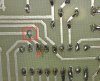
at you previous post you say it could be the PCB? how can the PCB cause such a problem? is it stray capacitance?...
hi lynx,
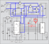
I assume that on your version of the LCF meter that you have the SET push button connected.? and that you carry out the Correction procedure as explained in the pdf.?
yes i did..
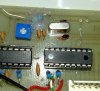
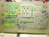
I have built the inductor osc section and it works OK, testing using a number of 4011 gave wide differences in the base frequency [ ie: when the test probes are shorted together]
The 10Kpot has a VERY wide range of frequency settings, I guess thats why the SET push button is used before measuring.
The base 4011's frequency outputs remain stable enough, over many tens of minutes.
mine can't remain stable.. :/
at you previous post you say it could be the PCB? how can the PCB cause such a problem? is it stray capacitance?...