Continue to Site

Welcome to our site!

Electro Tech is an online community (with over 170,000 members) who enjoy talking about and building electronic circuits, projects and gadgets. To participate you need to register. Registration is free. Click here to register now.

  • Welcome to our site! Electro Tech is an online community (with over 170,000 members) who enjoy talking about and building electronic circuits, projects and gadgets. To participate you need to register. Registration is free. Click here to register now.

HELP Needed!! - 7 Segment LED counter (74LS90 TTL)

Status
Not open for further replies.

kwon

New Member
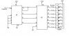
(1)There is a major problem with the 7 segment LED counter (using 74LS90 TTL BCD counter IC & 74LS47 TTL seven segment display driver IC). I have built one but it start at 1 rather than 0. Then i tried building another same one and this time it start with '5' (i have tried building it again and again but it still start at '5'). I have tried to combine the two circuit and I am getting '51' (as the first circuit start with '1' & the second circuit start with '5') but i want it to start/begin at 00(zero). I have made some research on the 74LS90 TTL BCD counter IC, and found out that using pin 1&2 and 6&7 can reset the counter. But I have problem figuring out the connections. I am not even sure wether resetting it will give make it into 00(zero) or reset it to '51'. (everything was done on a brick board and tested on a 'logic trainer' using 5V).

(2)There is another funny thing about this counter. Every time I off the main power source, it will randomly show a number before turning off and if I turn it on too fast(right after I turn it off) it will begin with another number (lets say, normally it begins with '5', when turned off-on too fast it will start with '9'). Is there an explanation to this?

Is there anyone able to solve my problems especially problem (1)... hope to get a reply as soon as possible. Thanks.
 

Attachments

  • 7segment_led_counter_116.jpg
    7segment_led_counter_116.jpg
    17.1 KB · Views: 2,331
When You switch off the psu, the filter capacitor slowly discharged by circuits. In this time the cct work randomly. For switch-on reset use an RC component on reset pins. The 100nF filter cap need for all IC supply pin.
 
I agree with Sebi. You did not have a "reset at switch on" circuit or a supply bypass capacitor.

With no reset, it will assume a random state at switch on. With no bypass, odd things can happen due to switching transients.

Len
 
I will try modifying the circuit then. Thanks guys... :D

If there is anyone with other solutions or able to improve/modify this circuit to a much better one, please feel free to post here.

Thanks again.
 
kwon said:
I will try modifying the circuit then. Thanks guys... :D

If there is anyone with other solutions or able to improve/modify this circuit to a much better one, please feel free to post here.

You could improve it by inserting a Hex Schmitt Trigger IC, a 74LS14.

Connect the output of one Schmitt to the reset pins (pins 2 & 3) (having first removed the resistor and capacitor) and connect a capacitor from the input to gnd and a resistor from that input to Vcc. The same resistor and capacitor will do.

When the power is switched on, the capacitor will be discharged and so the output of the Schmitt will go high, thus resetting the counter. When the capacitor has charged to the + threshold of the Schmitt, the output will go low thus removing the reset.

Len
 
I think that by connecting pin 12 to pin 1 of the counter, what you are actually doing is preventing the counter from actually counting no matter what the clock input is, because the two clock inputs must be falling low to make a count happen. When the counter is reset, Pin 12 is high, and pin 1 must be low in order for the count connection to work. Why not just tie pin 1 to ground?
 
mstechca said:
I think that by connecting pin 12 to pin 1 of the counter, what you are actually doing is preventing the counter from actually counting no matter what the clock input is, because the two clock inputs must be falling low to make a count happen. When the counter is reset, Pin 12 is high, and pin 1 must be low in order for the count connection to work. Why not just tie pin 1 to ground?

No.

Read the data sheet.

pin 12 is the output of a divide by 2 counter, pin 1 is the input of a divide by 5 counter.

2x5 = 10.
I guess that is why it is called a decade counter.

JimB
 
Sebi said:
When You switch off the psu, the filter capacitor slowly discharged by circuits. In this time the cct work randomly. For switch-on reset use an RC component on reset pins. The 100nF filter cap need for all IC supply pin.

I have tried modifying the circuit according to what Sebi did but it doesnt seems to work. Infact the 7 segment display didnt even light up. Can someone tells me what is wrong? Can someone teachs me how to add a 'reset at switch on' to the circuit.

Actually, i didnt used the 1uF cpacitor but 2.2uF instead bcos i couldnt get the 1uF. Is that the reason why it didnt work? But i think that is not the reason. Can someone please guide me?
 
I have finally able to add a reset switch to the circuit by just connecting pin 2&3 (74LS90) to another switch instead of connecting the two pins to ground. I have to first on the switch '1' in order to get 0(zero), then i need to turn the switch off '0' because the counter only counts when the pin 2&3 is low, '0'. But i would still prefer it to reset on its own to zero when starting rather than control by a switch. Is there a way? Anyone has any ideas?
 
kwon said:
But i would still prefer it to reset on its own to zero when starting rather than control by a switch. Is there a way? Anyone has any ideas?
I told you how to do this in my previous post.

Len
 
I agrre with Len, the schmitt-trigger solution always better. The capacitor value should be higher.
 

Attachments

  • 7segment_led_counter_116_160.gif
    7segment_led_counter_116_160.gif
    5.5 KB · Views: 1,394
I am having a problem with 7490 too. Like Kwon I am doing the same circuit. The my clock is generated by LM555, and its pin number 3 is at the pin 14 of 7490, but when I turn on the circuit, the leds(I used 4 leds with resistoir series and the anode is connected to the outputs of the count) bright but the three fisrt led shines and the forth is off. The leds swicths but the I have 1110 always. I connected the pins 2&3 and 6&7 to the ground. When i simulate a clock connecting the clk in Vcc and after the ground, random results appear. Does anyone knows what it can be ?

Thanks guy
 
How did you make it start on 1 instead of 0. I have had this dilemma on my dice toy project. I have several logic gates to randomise the LED's to make it look a real dice. When I turn on the circuit, the LED automatically stars at 1 and the 7 segment display stars at 0. There is a difference of 1 between the 7 segment display and what the LED's show.

Thank you in advance
 
Last edited:
How did you make it start on 1 instead of 0. I have had this dilema on my dice toy project. I have several logic gates to randomise the LED's to make it look a real dice. When I turn on the circuit, the LED automatically stars at 1 and the 7 segment display stars at 0. There is a difference of 1 between the 7 segment diaply and what the LED's show.

Thank you in advance

If you'll notice, the thread to which you are replying is several years old.

However, the question still comes up.

7490's are very susceptible to spikes and glitches on the power rails. Any circuit using this counter should be liberally by-passed with capacitors across the rails. Electrolytics in the 100 µF range work very well. Nearly all count problems will be solved with this fix.

Good luck.
 
I am not using a 7490 chip rather a 4026 decade counter and a 4017 decode decade counter. I needed something like a chip, e.c.t to advance the 7 segment display by 1 at the start

Thanks in advance
 
Last edited:
I am not using a 7490 chip rather a 4026 decade counter and a 4017 decode decade counter. I needed something like a chip, e.c.t to advance the 7 segment display by 1 at the start

Thanks in advance

Post your circuit so we know what you have done.

Here is a "Digital Dice" circuit that I built some years ago.
 

Attachments

  • Digital Dice_1.gif
    Digital Dice_1.gif
    12.2 KB · Views: 786
led counter

i am using same cct to generate count from 0-99. Doing this by grounding 2-3 and fixing a 1k resistor b/w shorted 2-3 and shorted 10-6-7. Capacitor used is of 1micro f. Please guide me as to where is reset switch placed in cct and how is it connected to the capacitor. I would be grateful if you can post the correct circuit diagram. Thank you.
 
Status
Not open for further replies.

New Articles From Microcontroller Tips

Back
Top