Electro Tech is an online community (with over 170,000 members) who enjoy talking about and building electronic circuits, projects and gadgets. To participate you need to register. Registration is free. Click here to register now.
Welcome to our site! Electro Tech is an online community (with over 170,000 members) who enjoy talking about and building electronic circuits, projects and gadgets. To participate you need to register. Registration is free. Click here to register now.
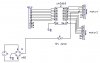
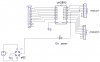
i had designed the circuit. can this can this control two stepper motors using parallel port? can u please give a stand alone driver so that i can test the circuit without using parallel port. are there any problems in my circuit?
It looks like you are coming off pin 1 of the parallel port which is the Strobe. The Data Pins are pins 2 through 9 which are D0 through D7. As to a stand alone circuit to simulate the parallel port? I have no idea. Also, the drawing could be larger making it easier to read. The way you posted it, it is hard to read.
will this be ok? stand alone or dumb circuit like the use of 555 timer to control the speed and direction by using switches instead of parallel port. thanks
You need a 12 VDC power supply. I don't know why the zener is in there. Even if you were using the zener to regulate to 12 V you would need a series resistor in there with the zener diode. Also if the motors each drew just 1 amp you would need at least a 24 watt zener. Get rid of the zener and get a 12 volt supply in there. Stepper motors do not need a fancy well regulated supply. Any decent 12 volt supply that can easily supply the needed current will work.
I don't get your use of pin 10 on the darlington? Pin 10 is common for the free wheeling diode array.
pin 10 is where i supplied the voltage and the common of the stepper motor is also connected to the supply.. am i right? i can see this in most of the stepper motor driver circuits.. thanks for the help
If you only want to drive the motor without a computer, one of these kits will do it; **broken link removed**
If you Google QK179 many other places sell them or some thing similar. Even Ebay sells them.
This site uses cookies to help personalise content, tailor your experience and to keep you logged in if you register.
By continuing to use this site, you are consenting to our use of cookies.