Continue to Site

Welcome to our site!

Electro Tech is an online community (with over 170,000 members) who enjoy talking about and building electronic circuits, projects and gadgets. To participate you need to register. Registration is free. Click here to register now.

  • Welcome to our site! Electro Tech is an online community (with over 170,000 members) who enjoy talking about and building electronic circuits, projects and gadgets. To participate you need to register. Registration is free. Click here to register now.

Help me build a two step sequencer

Status
Not open for further replies.
The Hex Schmitt Trigger will invert the outputs, right? Is there a special way to connect it? Would you recommend a particular one?

At this time I'm looking also for a Parallax Basic Stamp. Though a bit overkill it would do exactly what I want, when I want.
Any thoughts on this? Can I drive a relay directly from the output ports of the BS2?
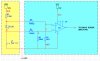
 
The 40106 Hex Schmit trigger IC will do all the timing for you and all you have to do is add a buffer to the outputs to drive 2 relays.

I have covered all of this on my web site under Chip Data E-Book:

Colin Mitchell
 
Last edited by a moderator:
The dual 555 circuit should work if you add an RC power-on reset to the reset pins on the 555s.
 
Hello again.
I ended up using a Basic Stap 1 microprocessor.
I have a new problem.
How can I check if a LED is already lit and if not, give a HIGH (or LOW, doesn't matter) signal to the microprocessor?
I found this component on the net: High-Side Measurement
CURRENT SHUNT MONITOR - INA38 (Amplifiers and Linear - Current Shunt Monitors - INA138 - TI.com).

Any one has another idea, maybe a simpler one?
Thank you.
 

Attachments

  • IMG_0202.JPG
    IMG_0202.JPG
    402.6 KB · Views: 130
  • IMG_0206.JPG
    IMG_0206.JPG
    371.9 KB · Views: 131
  • IMG_0207.JPG
    IMG_0207.JPG
    280 KB · Views: 110
Last edited:
Those symbols in your schematic don't look like LEDs. How much LED current are you using? What is the forward voltage drop of your LEDs? Are you going to feed the results of the current sense back to the Basic Stamp?
 
How on earth are you going to be able to program a "stamp" when you don't have the ability to reply to my suggestion to use a Hex Schmitt Trigger?

I have been a teacher for 30 years and I can tell the capability of a person at the age of 14. And a person does not change.
If the don't listen at 14, they don't listen at 60.
 
Thank you for your reply.
Actually, I already programmed the Basic Stamp and it works exactly as I wanted it to work. The "Stamp" responds to the GA pushbutton being pushed by activating the two relays in sequence.

I discarded the sugestion given here to use the 555 for two reasons: because adding a hex schmidtt trigger would create a more complex circuit than what I wanted originaly and because I wanted to take the chance to use a Stamp. Beside this, I coldn't couch the 555 to have a delay between them.

Anyway, by using the Stamp I figured that I could add a event check: the idea is to check if the condition that the relay is going to trigger is aleeady active. Because if it is, the action of the relay would be to deactivate the mode I wanted to engage, something I didn't want to happen.

So if I colud let the Stamp check if a mode indication LED is already lit, the program would bypass that step.

The LED is powered from a 12v bus trough a 3.3k resistor, and is connected to the ground by a CAN COMBO BOX, a device that is part of the simulator. This box receives the order to turn the LED on trough the pushbuttons that the relays on my project shunt.

The schematics I presented above do not include these "LED monitoring" feature.

My question is: how can I make the Stamp "see" that a LED is already lit on a separate system, one that is not the source of power to my project, but that share the same GROUND.

Thank you and my apologies for the extension of the post.
 
This is the PBASIC code I'm using.
I'll change the schematic to include the changes I wanted to implement and post it here latter on.

Code:
' {$STAMP BS1}
' {$PBASIC 1.0}

INPUT 0                         'Makes Pin 7 an Input pin - GO-AROUND P/B
INPUT 3                         'Makes Pin 10 an Input pin - HDG LIGHT ON
INPUT 4                         'Makes Pin 11 an Input pin - IAS LIGHT ON
OUTPUT 1                        'Makes pin 8 an Output pin - ACTIVATE HDG
OUTPUT 2                        'Makes pin 9 an Output pin - ACTIVATE IAS

START:                          'Loop label
  IF PIN0 = 0 THEN START        'If GA push-button not pressed, keep checking
  IF PIN0 = 1 THEN HDG          'If GA push-button pressed goto HDG label

  HDG:
    IF PIN3 = 0 THEN IAS        'Check if HDG was already active. If so, goto IAS
    HIGH 1                      'Set Pin 8 to HIGH, activating the HDG mode
    PAUSE 700                   'Wait for 0.7 seconds
    LOW 1                       'Set Pin 8 to LOW
    PAUSE 100                   'Wait 0.1 seconds

  IAS:
    IF PIN4 = 0 THEN WAIT      'Check if IAS was already active. If so, restart the process
    HIGH 2                      'Set Pin 9 to HIGH, activating the HDG mode
    PAUSE 700                   'Wait for 0.7 seconds
    LOW 2                       'Set Pin 9 to LOW

  CHECKGA:
    IF PIN0 = 1 THEN CHECKGA    'Check if GA P/B still pushed. Is so, wait for release
    GOTO START                  'If GA P/B released, resume loop from Start
 
Last edited:
You can do all this with one Hex Schmitt trigger ($1.00) and gate one of the gates from the LED.

But you have to explain exactly what you are trying to do and what you want the gating to achieve.
 
Thank you for not quiting on me.
This is what I want to do:
I want one of the input pins of the BASIC STAMP 1 to go high if a LED on a separete panel comes ON.
The Stamp is powered by a 5 volts power supply and the LED is on a separate circuit, powered from 12 volts by a 3.3k Ohm resistor.

Both circuits share, however, the GROUND (-).

Can this be done?

What would be the simple solution to this problem?

I don't know if this helps but I can measure the voltage between the + side of the LED and the GROUND when the LED is OFF as 12 Volts. When the LED is ON it drops to 9.8 Volts.

Here is the schematics of the system that controls the LED that I want to monitor.

Micro switches S5 and S1 are the ones that my relays shunt to activate the HDG and IAS modes. As a result, the HDG and the IAS LED lit up. They are not represented in this drawing but you can use any of the LEDs that are here as a correct example of the ones I want to monitor.

So, how do I monitor if one of these LED is already lit up and pass that status to an input pin of a Basic Stamp as an HIGH level?
 

Attachments

  • FrascaB200 - Autopilot.pdf
    434.3 KB · Views: 138
Last edited:
Hello everybody.
I'm still cracking my head with this problem.

I looked at a opamp 741 as a possible solution.
I saw a circuit where a 741 is used to measure the current on a 1 Ohm resistor. I've created a circuit with this approach and would like to know your opinion if it will work if I measure the current on the LED instead.
The purpose of the circuit is to give a HIGH signal on the output if the LED is ON and a LOW if it is OFF.

Thank you

schematic-jpg.27180
 

Attachments

  • schematic.jpg
    schematic.jpg
    136.9 KB · Views: 268
That should work if you don't mind having a little current flowing through the LED when the switch is off, except a 741 won't handle the low input voltages. Use a LM393 (dual) or LM339 (quad) comparator. The output is open collector, so put a 10k pullup to +5V.
 
Thank you Ron. I have one of those in my box. I'll give it a try.
Any advice regarding the inputs of the comparator? As I mentioned before, the + side of the LED drops from 12 to about 9,8 Volts when the LED is ON. Should I use any resistors for the input pins of the comparator?
 
Thank you Ron. I have one of those in my box. I'll give it a try.
Any advice regarding the inputs of the comparator? As I mentioned before, the + side of the LED drops from 12 to about 9,8 Volts when the LED is ON. Should I use any resistors for the input pins of the comparator?
If your resistor is really above your LED as you show it, the voltage at the anode should be about 2V when the switch is closed. If you have 9.8V on the bottom wire when the LED is on, maybe the resistor is below the LED. Or maybe there are several LEDs in series.
In any case, the resistors you showed should still be used for the comparator.
 
Hello everyone.
The LM393 did the trick. :)
It works like a charm.
Thank you Roff.

Here is the schematic with the 393 in place:
simulator_comparator-jpg.27229


Here is a Photo of the breadboard with the monitored LED off (the green one that is connected to 12V) and as a result the white LED is also off. The heat sink is a 7805 for the 5V:
img_0218-jpg.27233


And here is a photo with the LED on, resulting on a 5V output from pin 1 driving the white LED.
img_0217-jpg.27232


Now I'll join all the circuits together and create a PCB for a test drive.

Thank you all for the help.
 

Attachments

  • Simulator_Comparator.jpg
    Simulator_Comparator.jpg
    130.7 KB · Views: 321
  • IMG_0217.JPG
    IMG_0217.JPG
    480.3 KB · Views: 289
  • IMG_0218.JPG
    IMG_0218.JPG
    476.8 KB · Views: 256
Unless your Basic Stamp has an input pullup resistor, you should add one to the output of the comparator. Thr comparator is basically just a switch to ground (open collector), which has no pullup.
 
Oh yes...:confused:
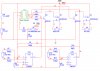
, I omitted those on the schematic but I planted them on the breadboard.
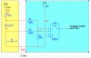
Here's the final schematic with everything put together:

final_schematic-jpg.27235
 

Attachments

  • final_schematic.jpg
    final_schematic.jpg
    207 KB · Views: 280
Why don't you simply connet the bottom of the LED to the input of the micro via a 100k resistor?
 
Last edited:
Status
Not open for further replies.

Latest threads

New Articles From Microcontroller Tips

Back
Top