Continue to Site

Welcome to our site!

Electro Tech is an online community (with over 170,000 members) who enjoy talking about and building electronic circuits, projects and gadgets. To participate you need to register. Registration is free. Click here to register now.

  • Welcome to our site! Electro Tech is an online community (with over 170,000 members) who enjoy talking about and building electronic circuits, projects and gadgets. To participate you need to register. Registration is free. Click here to register now.

Help me build a two step sequencer

Status
Not open for further replies.

luisr320

New Member
Hello everyone.
I've been messing with electronics for some years now.
My level of knowledge on these matters are basic.
I need to build a small circuit that acts as a two step sequencer.
I want it to remotely actuate two different press buttons in sequence by only pushing a third pushbutton. They must be actuated always in the same sequence. And if I push the pushbutton again it should repeat the sequence again.
I'm talking of a 5 volt circuit.
Too confusing? Sorry about that.

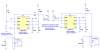
I looked at a decade/counter as an option but it seems overkill and I don't know how to stop the counting if it uses a 555 to feed pulses.

Any ideas?
Thank you
Luis
 
Hello Collin. Thank for your prompt reply.
I think that relays would be the simple option. So, yes, relays. That would avoid all the problems of sinking currents, which I'm not sure about their magnitude, alas being on the very low side, surely.

This project is for a flight simulator, to engage a two step mode, that requires the pilot to push two buttons in sequence on the Auto-Pilot panel. I want to change this action by a single pushbutton action. The relay poles would be connected in parallel with the pushbutton that must retain their original function individually.

Each pulse from the relay must last about 1 second, after which the contact must open again reseting the system.

Regards,
Luis
 
Last edited:
Hello again.
I can't find the circuit. Is there an area to download images?
Thank you for putting up the effort.
Regards,
Luis
 
Hi. The circuit was there all along. I couldn't see it because I didn't login on the Forum.
So, if I understand it correctly, the 100uF capacitor on the 2nd transistor's base determines the amount of time between both relays work, correct? But that forces the pilot to keep holding the pushbutton long enough until the second relay starts to work.

My idea is that the sequence should start as soon as the pilot pushes the button, even if he does so just for a split of a second and then releases the button.

Anyway, it's a good start. Sometimes all we need is someone to show us the way to go.
Thank you very much.
Regards,
Luis
 
I use a very old Paint-6 program as I have used it for the past 8 years and I don't want to learn enything else.

I have used it on my website:

<mod edit: self promotion deleted. If you have content to share, please post directly to ETO. Do not link to your own personal website>
 
Last edited by a moderator:
Here is a circuit for you to try. The values will have to be adjusted:
You should add a 1N4148 diode across each relay coil, anode to ground.
I think a bipolar 555 running on 5V is marginal for a 5V relay, due to the high level not reaching the positive rail. A CMOS part might be better for low-current coils, such as reed relays.
He could also use a CMOS 556, which is basically a dual 555.
 
Here is the circuit with protection diodes across the coil of each relay.
You will need a 12v supply as the 555's only produce about 10v on output pin 3 when HIGH.
You can use a dual 555 (556)

**broken link removed**
 
He said he was talking about a 5 volt circuit. I don't know if he meant that only the relay contacts will be switching a 5 volt circuit, or if he meant he intends to power the oneshots with 5V.
 
There is nothing left on the output of a 555 if you use a 5v circuit.
I assumes the simulator would be 12v. Like all training aircraft.
 
There is nothing left on the output of a 555 if you use a 5v circuit.
I assumes the simulator would be 12v. Like all training aircraft.
I suggested CMOS 555s in a previous post. If you use relays with low-current coils, they should be fine. The contact loading is apparently minimal.

I don't know nuttin' about no training aircraft.:D
 
Last edited:
I'm trying the circuit on multisim and the first relay is alway on after the first pulse... :(
I found this PDF on the NET.
www.jaycar.com.au/images_uploaded/relaydrv.pdf
It seems that the Relay is connect to the positive side of the circuit.
What would be the difference?
I simulated it (my version) in LTspice, and it worked fine.
The circuit you posted is driven differently. When used as a monostable (oneshot), the 555 goes high when triggered.
 

Attachments

  • 555 sequenced oneshots.PNG
    555 sequenced oneshots.PNG
    33.3 KB · Views: 157
I breadboarded the 1st 555 to check what happens.
When I connect the power (12V), the OUT pin of the 555 rises immediately to 12 V. When I join the two long yellow wires, simulating the pushbutton action, the voltage drops to zero, for about 1 second. This would be exactly the opposite of what I wanted to happen.
I'm measuring the OUT voltage by connecting the (+) probe of the voltmeter to the (+) of the power supply and (-) probe to the OUT pin of the 555. If I connect the probes the other way around, I get the same readings but with the polarity reversed.
What am I doing wrong here...???
IMG_0289.JPG
 
I breadboarded the 1st 555 to check what happens.
When I connect the power (12V), the OUT pin of the 555 rises immediately to 12 V. When I join the two long yellow wires, simulating the pushbutton action, the voltage drops to zero, for about 1 second. This would be exactly the opposite of what I wanted to happen.
I'm measuring the OUT voltage by connecting the (+) probe of the voltmeter to the (+) of the power supply and (-) probe to the OUT pin of the 555. If I connect the probes the other way around, I get the same readings but with the polarity reversed.
What am I doing wrong here...???
View attachment 26507
You need to measure across where the relay would go. Negative probe to ground (negative side of power supply), positive probe to pin 3 on the 555.
 
You have to let the 555 settle down.
This involves it going through its first cycle when the power is first applied. This is one of the problems of a 555.
After that, it operates as required.
 
If this is not acceptable in a real-life situation, the circuit will have to be re-designed around a hex Schmitt Trigger.
 
I found this schematic on a book called "Engineer's Notebook II" by Forrest M. Mims, III.
Do you think this will do the trick?
The other schematics that were proposed here all start with the OUTPUT on a high level. Even after letting the 555 setle it will always start high and go low when i press the pushbutton.
sequencer.jpg
 
All the 555 circuits start by going through the sequence of producing a HIGH on the output.
As I said beore, if you don't want to have this happen. you will need to have a circuit designed around a hex Schmitt Trigger.
 
Status
Not open for further replies.

New Articles From Microcontroller Tips

Back
Top