Continue to Site

Welcome to our site!

Electro Tech is an online community (with over 170,000 members) who enjoy talking about and building electronic circuits, projects and gadgets. To participate you need to register. Registration is free. Click here to register now.

  • Welcome to our site! Electro Tech is an online community (with over 170,000 members) who enjoy talking about and building electronic circuits, projects and gadgets. To participate you need to register. Registration is free. Click here to register now.

Help!! IR break beam sensor output as button press on IPAC

Status
Not open for further replies.

virtualmark

New Member
Help wanted please. Total newbie here and seeking advice.
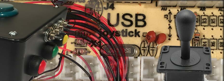
Currently building an arcade machine of sorts and I have acquired an ARC controller (https://core-electronics.com.au/usb...qtuO9ud5Jo9YaGlWF3hRv2SymmskkF-caAoPnEALw_wcB
And IR beam break sensors (https://core-electronics.com.au/ir-break-beam-sensor-5mm-leds.html)

the break beam sensors are an open collector.
I want to wire them in to my IPAC game controller above as a button press and I am stumped.

I am sure this may be easy for someone but I have limited knowledge.

I have read I need a resistor on the signal wire if my board doesn’t have a pull up resistor

I’m not sure how I would wire up my one signal wire coming from the IR to my two board wires coming from the button connector so that it will register a button press when the IR beam is broken. ??
I have wired up the IR to the 5v sockets at the top of the boards (red sockets) and tested them but I am not even sure if this is how i would keep it?

Sorry if this post seems rushed it is written out of desperation.
Thanks in advance
6D38F9FF-0E6D-432F-B2D5-DB723BFE65D1.jpeg
FB0BB161-3347-40DF-B1D6-58316D27AA87.jpeg
 
Your open collector style sensors need +5V and ground (0V) connections,, then the output signal switches to ground.

The interface board has inputs that need switching to +5V, not ground.

If you want to trigger when the sensor turns on, you will need to add a PNP transistor and some resistors, or a P channel logic level FET and a single resistor to each input, to adapt the signals.


Or, if you want to trigger when the sensor turns off (when the beam is broken?), connect 5V power and ground, then connect the sensor output to the inner pin on the button input connector; the outer pin is +5V.

Also add a resistor between the two pins on the input connector so it will trigger the input when the sensor turns off.
Try 1K to start with, if that is at all erratic try 470 Ohms. From the IR sensor data, you could go down as low as 100 Ohms without risk of damage, but I'd try higher values to start with.

I found an article with a lot of info about that interface here, it shows how power is routed aroudn the connector pins and which are 5V vs input signals; look for teh image of the board with the red highlighted track.
 
Thank you!
I want it to trigger a button press when the beam is broken…
I will see what resistors I can find and start with the larger ones. I will connect the IR receiver output to the inner pin like you said and connect the resistor in between the two pins. This is the part I don’t really understand but hey it’s all about learning
 
Each input will have a resistor (or equivalent) to ground and connect to a logic input on one of the ICs in the unit (under the black blobs).

The resistor means the input pin is at or near 0V, logic "low" when a connected switch is not pressed.
When the switch is pressed, the input is held at 5V via teh switch, so the IC sees a logic high level.

Adding an external resistor that is significantly lower value than the one built in to the input circuit will pull the input to near 5V, enough to be seen as a logic high level as if a switch was pressed - but the input can still be connected to ground to pull it low.

The tricky part is finding what resistor value is needed to "override" the interal pulldown resistor and guarantee a high enough input voltage, without that being such a low value the current to ground the input becomes excessive.

Typically the internal pullup or pulldown in an IC is fairly high, equivalent to 10K or more; a 1K external resistor should pull the pin to somewhere near 5V so well above the usual input high level for most logic ICs. As long as the circuit on that board works like that, you shoudl be fine.

Out of curiosity, you could also measure the voltage across eg. a 1K resistor with that connnected (without the opto sensor) as the voltage across that can be used to work out the current from the internal resistor or pulldown circuit; 1V per milliamp with a 1K resistor.
 
Thank you so much you explained that really well and at my level! I will track down a few different sized resistors tomorrow as also measure the voltage across the input to get an idea..

out of curiosity could the IR sensor output be used to say trigger a relay or some other switch that I could then easily connect to the controller ?
 
The IR sensor it rated to switch up to 100mA; that's like a 50 Ohm load at 5V.

A 5V relay with a coil resistance higher than 100 Ohm should switch OK if connected between output and power. It must also have a "flywheel diode" connected across the coil; a rectifier or suitable signal diode rated more than 100mA, connected cathode to positive so it's not conducting when the relay is powered.

It could also switch many solid-state relays, as many types work from 3V upwards and can control large loads.
 
Ok great thanks. Would something like this work? Or should I stick to one listed as a solid state relay?

This is only a backup as I will try the local for some resistors today
Thanks again!!!
 
It would work; it's massive overkill to just switch the USB module inputs though - I thought you meant for other applications.
A conventional solid state relay is for switching large AC loads and would not work.

A simple relay or an optoisolator would work fine; my personal choice would be optoisoators - but that means soldering the parts together to make an adapter unit.

However, ready-built modules like the one you link to, with the relay and drive circuits, screw terminals etc. all included, are cheaper than separate relays or parts for an opto board.

eg. This is a four channel relay version for a similar price:
 
No it’s literally just the simulate a button press on the USB input board. Hopefully the resistors can work and I don’t need this option
Thanks for all your help I will hopefully have problem solved by end of day
 
Status
Not open for further replies.

Latest threads

New Articles From Microcontroller Tips

Back
Top