Continue to Site

Welcome to our site!

Electro Tech is an online community (with over 170,000 members) who enjoy talking about and building electronic circuits, projects and gadgets. To participate you need to register. Registration is free. Click here to register now.

  • Welcome to our site! Electro Tech is an online community (with over 170,000 members) who enjoy talking about and building electronic circuits, projects and gadgets. To participate you need to register. Registration is free. Click here to register now.

Help: 3-phase sine generation lookup-table microcontroller

Status
Not open for further replies.
Hmm.. yeah. You can't use the negative values in the PWM module to set duty cycle.. it does not work properly.

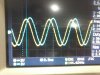
I would still use negative numbers int the LUT though, because that is more natural presentation of sine signal (it oscillates around zero).
 
Yes but that would exceed my top value limit (250) if 125 were to be added.
Anyways, i am checking this on a DSO as i type and the results are not good

I now use 6 channels of PWM.
Top 3 drives are even numbered PWM and lower 3 are odd numbered.
I now update duty as
CH0 = CH3 , CH2=Ch5 , Ch4=Ch5
and offset at Table+11, Table+22 and see cross conduction in all vertical limbs :confused:

EDIT : i FOrgot to mention that i just replicated the first 16 values as next 16 values in the LUT (So 2 humps in 180deg)
 
Yes but that would exceed my top value limit (250) if 125 were to be added.

How? If the largest value in your LUT is 125? How do you go over 250 by adding 125?
 
Since the compiler changes the negative values
-24 as 232
and when i add 125 to 232 it crosses 250

The compiler should be able to calculate 125 + (-24) correctly so that the result is 101.
Make sure that the sine table type is a "signed char"
 
I wish that happened!
While in my debugger window i see the LUT variables and all are positive values as i mentioned earlier , before i hit 'RUN'
what did you think of my other post #22 ?

EDIT : I Appreciate your patience and apologize for being all inquisitve with silly questions as they may seem to you.
But thanks for getting involved :)
 
I now update duty as
CH0 = CH3 , CH2=Ch5 , Ch4=Ch5
and offset at Table+11, Table+22 and see cross conduction in all vertical limbs :confused:

I have no idea what you are trying to do here.
 
Ok let me be a bit expansive
3 PWMs have 3 sets of Duty values for updation
sintable[Dutycycle1] or sintable[Dutycycle2] or sintable[Dutycycle3]

the first channel updates its value from say
sintable[0]
Dutycycle2 = Dutycycle1+11 , Dutycycle3 = Dutycycle1+22
second channel updates value at a table offset of 11 and the third at an offset of 22

which i calculated by simple math at 120 and 240 deg (since i have a 32 variable LUT for a 360 deg wave)

i update CH0 as sintable[Dutycycle1] while Ch2 = sintable[Dutycycle2] while Ch3 = sintable[Dutycycle2]

these are upper limbs and the lower limbs i just complement the upper switches value.
 
What confuses me is the way you use Dutycycle to describe phase. Shouldn't the sineTable return dutycycle value according to the phase?

and what is this supposed to do then:
CH0 = CH3 , CH2=Ch5 , Ch4=Ch5
 
Hello
Yes ,apology for confusing you.
But Dutycycle_n would be the index of the sintable[] array
CHn = PWM channel
CH0 is the R channel should be equal (?) to Y^ = CH3
CH2 is the Y channel should be equal to B^ = CH5
Ch4 is the B channel should be equal to R^ = Ch1 (sorry for the typo on the earlier post)

I am attaching 2 waveforms as seen on DSO.
First is R vs R^ yellow is R and Blue is R^ (should be out of phase, since in same limb) 1.jpg

Second is R vs Y^ (should've been equal, since in diagonal limb)2.jpg
 
I don't understand why don't you just cycle though the sinetable and use that to update the channels:

CH0 = sintable[Dutycycle]
CH2 = sintable[Dutycycle + 11]
CH4 = sintable[Dutycycle +22]

Then make sure the other channels are complementary of these..

why you copy duty values from other channels?
 
I changed something .What i did was
CH0 is complement of CH1
Ch2 is complement of CH3
CH4 is complement of CH5
Complement meant Both are Edge aligned PWM but one channel has High true pulses whereas the other one has Low true pulses. So now naturally when a same limb has mandatory complementary signals.
The next limb has 120 deg shifted signals and the 3rd limb has 240 deg shifted signals.

The waveforms i showed were with this scheme.

But i dont understand or rather how do i validate whether this is working correctly? maybe it is and i am unnecessarily going into unwanted areas
 
I changed something .What i did was
CH0 is complement of CH1
Ch2 is complement of CH3
CH4 is complement of CH5
Complement meant Both are Edge aligned PWM but one channel has High true pulses whereas the other one has Low true pulses. So now naturally when a same limb has mandatory complementary signals.
The next limb has 120 deg shifted signals and the 3rd limb has 240 deg shifted signals.

That sounds good. You should be able to verify the performance with an oscilloscope.
 
No, they are 120 degrees apart in phase.. at some points they switch equally and at some points they do not.. depends on the phase.
 
Okay misterT

I think i understood it all, i and i think this is complete.
Tomorrow i will check it on IGBTs

You have been a great deal of help :)

Thanks and best regards
 
why don't you just add the 128 to the values stored in your table to begin with, and not have to do it at the time you update the values.
 
why don't you just add the 128 to the values stored in your table to begin with, and not have to do it at the time you update the values.

That is a good way to optimize if you need to, but I think it is better to keep sine values symmetrical around zero. That is the "natural way" to represent sine signal. It is a matter of "style" more than functionality. Both ways work.
I would change the name of the table to something else if the offset was added to the table values. It would not be a proper sine anymore. I know it sounds nitpicking, but in the long run it makes a difference. Certainly separates pros from hobbyists.
 
Last edited:
Status
Not open for further replies.

New Articles From Microcontroller Tips

Back
Top