Electro Tech is an online community (with over 170,000 members) who enjoy talking about and building electronic circuits, projects and gadgets. To participate you need to register. Registration is free. Click here to register now.
Welcome to our site! Electro Tech is an online community (with over 170,000 members) who enjoy talking about and building electronic circuits, projects and gadgets. To participate you need to register. Registration is free. Click here to register now.
I want to understand how audio amplifiers with discrete components work...
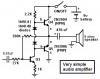
I found the following Headphone amp schematic which is the most simple i could get and i hope that someone can step by step explain it to me!
That's a tiny class A amplifier, so not really a good subject to try and learn from.
But essentially the first transistor is a boot-strapped common emitter amplifier, and the second is a normal common emitter amplifier. The third transistor (at the top) is a constant current load for the output transistor.
Can't say I think much of it, no negative feedback at all.
Nigel, you are too kind. It looks like crap to me. There is no AC or DC feedback (well, a little local feedback in the emitter of the input transistor). As you said, the output stage is a common emitter with a constant current load. What kind of luck would you have to have for the output stage to be biased in the linear range? Even if it were, you would wind up with a very high output impedance - not exactly ideal for driving headphones. Whiz needs to find a better circuit to study. Unfortunately, I can't recommend one. I'll bet Audioguru can.
It is a horrible amplifier.
Because it doesn't have DC negative feedback then the operating points of its first and third transistors could be with them cutoff or saturated or anywhere in between.
Because it doesn't have AC negative feedback then its gain could be almost anything and its distortion will be high.
oh WOW!!! Audioguru you made me excited!!!
this schematic is really simple and i think i can understand it all
of it without your help, so here i start!
0,47uF is a coupling capacitor for cutting any DC and for not letting
any resistive loads interfere with the bias of the Q3 transistors.
27K is a the resistor to bias Q3
390K is the negative feedback resistor
Q3 is the pre amplfication stage (voltage amplification)
the diodes i don't know exactly what they are doing there
The R2 regulates the emitter/collector voltage
Q4/Q5 is the final stage... two transistors in push/pull which each one
of them handle half period negative or positive.
470uF is an output capacitor to remove DC offset...(but probably destroys the frequency responce?)
guys is that simple to understand an amplifier with descrete components?! if yes why some schematics i have seen are huge?
I want to know some more classes other than AB... btw the schematic
i uploaded it's more difficult for me, i don't understand it.... so how am i understand more difficult schematics?
thank Audioguru!!! you're great!!! (i also thank the other guys too...)
No. It doesn't have the transistor's DC base current in it. The 390k negative feedback resistor biases Q3. The 27k resistor helps set the gain of the amplifier.
They turn on the two output transistors slightly to avoid crossover distortion. The diodes voltage changes the same way the transistors voltage changes with temperature.
It prevents DC in the speaker. Its cutoff frequency (half power) into an 8 ohm speaker is 43Hz. Use 2200uf for a cutoff frequency of 9.1Hz.
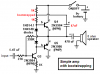
The 2.2k resistor does a poor job biasing Q4 because as the signal voltage rises at its base then its current is reduced.
This "bootstrapped" modification allows constant current in the biasing resistor for Q4 (the voltage where the two 1k resistors join actually swings above the power supply voltage because the voltage across the 47uF capacitor remains constant). Then the output power is much higher and the distortion is much less.
yeah i mean that farther amplifies the imput voltage... works like a buffer?
audioguru said:
They turn on the two output transistors slightly to avoid crossover distortion. The diodes voltage changes the same way the transistors voltage changes with temperature.
hmm if i understood correctly it is both regulates the collector and also the base at once?!
I liked very much this simple discrete amplifier... and i think i'll build it... can i learn specifications? output power/freq response/SNR? i know that my question is funny but i'm very excited...
about the second schematic with the bootstrap thing... i'm still looking at it! you changed everything...
just now i've made a speculation for the probably silly questions i'm doing at the end...
The 2N3904 is a very small transistor so it can't handle much current...
and also too much voltage probably will make it too noise! so i guess it outputs much less than 0.5W, now about the others i guess i can't figure out easily.
If the voltage gain of Q3 was thousands without negative feedback then its gain would be reduced to 390k/27k= 14.4 with negative feedback. The gain of Q3 is much less so the voltage gain will be less than 14.4.
you mean it doesn't draw any current from the source right?
Look at crossover distortion in Google. Both push-pull transistors must conduct a little to avoid crossover distortion. The diodes are almost the same as a base-emitter transistor junction so they regulate the small current in both transistors to eliminate crossover distortion.
hmm if i understood correctly it is both regulates the collector and also the base at once?!
When Q3 turns on more then its collector voltage drops. When Q3 turns on less then its collector voltage rises. The current in the 2.2k resistor moves from the collector of Q3 to the base of Q4.
I liked very much this simple discrete amplifier... and i think i'll build it... can i learn specifications?
Don't make it. It is crap.
It uses the wrong transistors to drive an 8 ohm speaker. The 2N3904 and 2N3906 have a max current of 200mA which is a peak voltage of only 1.6V across the 8 ohm speaker. Then its max allowed output power is only 160mW.
The BC337 can replace the 2N3904 and the BC327 can replace the 2N3906. They have a max current of 800mA. If they don't melt then the amp will produce the max power available from only a 9V supply which is about 1W when it is bootstrapped.
There is a headphones amplifier on the internet that uses opamps with only 0.00008% distortion. Nobody can hear distortion so low.
It wasn't good enough for the designer so he added a DC load to the opamp so its output operated in class-A to reduce the crossover distortion. HA!
Audioguru ok i have better understanding of the first schematic...
and i also understand why you have these 2 diodes...
now about the second schematic... the bootstrap if i understood it correctly takes signal from the output and sends it to the base of the transistors?
i think i'm going to build this amplifier so i can see it working and understand it better... tell me what modifications to do without loosing the simplicity of the design! and without getting far from what i'm trying to understand with this design!! do you think something like a BD139/140 can make a better work?
i want to make it on a breadboard so i can work up to 12V/1A
The BD139/BD140 little power transistors have a max allowed current of 1.5A. That is the peak current of a sinewave with a power of 9W into 8 ohms.
An amplifier has a voltage loss at its output of about 2.5V. Then the peak-to-peak voltage swing with a 12V supply is 9.5V. Then an amplifier can make 3.5V RMS into 8 ohms which is a power of only 1.5W. The average power supply current is about 250mA.
The little power transistors have a low current gain like all power transistors. Then the transistor feeding them has a high output current which reduces its voltage gain and reduces the amplifier's negative feedback. Then the distortion is high.
Amplifiers usually use driver transistors to drive the power transistors so that the voltage amplifier transistor can have a high voltage gain, and a high amount of negative feedback can be used in the amplifier resulting in low distortion.
hmmm does it matter? i don't want it to hear music!
i have made many builds to enjoy myself.... DACs, LM3875 Gainclone amp, TDA1553Q amp etc... but this is the first time i'll make an amplifier which is not Chipamp... so it it wrong to start with something small that i can understand?
I think a great learning amp that works as a headphone amp is here:
**broken link removed**
Real common way of doing things from what I understand. Should drive any headphone on the planet. I've got parts for a (modified) version I am working on now.
I think a great learning amp that works as a headphone amp is here:
**broken link removed**
Real common way of doing things from what I understand. Should drive any headphone on the planet. I've got parts for a (modified) version I am working on now.
looks easy and very simular to what i'm studing here!!! but it uses
IC it's not totaly from discrete components and also i think it needs a PCB..
i don't think i can make it on a breadboard probably it will behave far
worst even than the amp that Audioguru advices me not to build.
This site uses cookies to help personalise content, tailor your experience and to keep you logged in if you register.
By continuing to use this site, you are consenting to our use of cookies.

")