Continue to Site

Welcome to our site!

Electro Tech is an online community (with over 170,000 members) who enjoy talking about and building electronic circuits, projects and gadgets. To participate you need to register. Registration is free. Click here to register now.

  • Welcome to our site! Electro Tech is an online community (with over 170,000 members) who enjoy talking about and building electronic circuits, projects and gadgets. To participate you need to register. Registration is free. Click here to register now.

Having trouble with LM2907 F/V converter

Status
Not open for further replies.

zhassan

New Member
HI everyone

I have seen that a lot of people have experience with this chip and i was able to find a lot to help me out but now i'm kind of stuck and need advice.
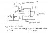
I'm using the 8-pin LM2907N-8. Attahced is the data sheet and circuit.

I'm getting the Vo of just 3.23 max with Fin of 5khz. The lower values are fine (1v = 1khz, 2v = 2khz and 3v = 3khz) approx but not getting the 4v and 5v out.
Even changing the voltage input doesn't make a lot of difference.
Freq input is square wave 5v pk-pk. R1= 20k, C1= 10nF, R= 1k & C2 = 1uF.
I did tried according to the data sheet but it was giving funny readings (very less) but i'll try it again as see what it does.

Plz give any suggestions and advice on it :confused:
 

Attachments

  • LM2907_F-V.pdf
    542.1 KB · Views: 679
  • V-F circuit view.JPG
    V-F circuit view.JPG
    40.3 KB · Views: 2,989
The maximum output voltage of your circuit is 2.3V less than the supply voltage. If the supply is only 5V then the guaranteed max output voltage is only 2.7V. Some ICs have a little less loss.
Increase your supply voltage.
 
Power supply increased

thanks for the reply. I have increased the power supply but it was still the same. However i got what i needed on pg 16 (changing techometer gain curve or clamping the min output voltage).
Its working fine :D in this config but i'm having current issues (when chip connected). when i use a potential divider for bring it from +12v to +10v.

any ideas? why?
 
A potental divider has terrible voltage regulation. The output voltage changes when the load current changes.
You need the supply voltage regulated at about 8V, not 10V.
You could copy the zener diode circuit in the datasheet or use an LM317 adjustable voltage regulator IC.
 
Are u sure bcoz on the data sheet it says +10V. I'll run some tests today to see how linear it is with +8v and +10v. Bcoz I have to display it on the LCD as well.
The potential divider is not working that well. I'll go for the zener option.
 
Are u sure bcoz on the data sheet it says +10V.
The circuits that have an output voltage when the input is zero Hz use a regulated 10V supply so that two resistors provide the offset voltage.
Do you want the output to have a voltage when the frequency is zero?
 
Got it working.

Do you want the output to have a voltage when the frequency is zero?

Sorry for the late reply. I didn't understand ur question right :confused:
I think the answer is 'NO' but wouldn't the chip not work until it receives a freq input? hmmm..
I'll test it first and see how the chip behaves.
However, I came to know that I had +15V on the other circuit board and instead or lowering it down it was better to just use it. So, I changed the Values to C1 = 1nf, C2 = 470nf & R1 = 66.67K (100K//200K). Its giving quite a linear Voltage out to freq out.
 
Last edited:
I have tested the F/V chip.


Well, it doesn't has any floating voltage when there is no Freq input going in. It seems fine :)
 
Last edited:
I think I forgot to mention from where I got the details for the linear Vout to Freq out. ITs on the data sheet on pg16 'Changing Tachometer Gain curve or Clamping the min output volts'.
 
Status
Not open for further replies.

Latest threads

New Articles From Microcontroller Tips

Back
Top