Electro Tech is an online community (with over 170,000 members) who enjoy talking about and building electronic circuits, projects and gadgets. To participate you need to register. Registration is free. Click here to register now.
Welcome to our site! Electro Tech is an online community (with over 170,000 members) who enjoy talking about and building electronic circuits, projects and gadgets. To participate you need to register. Registration is free. Click here to register now.
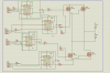
There are many things wrong here. The 555 is not the right part here.
The "gate resistors" should be closer to 10 ohms not 10k.
In green I drew the ground nodes. They must be connected together.
U1 and U2 do not connect to ground but live on the Source of Q1 or Q2. U1 must connect to the Source of Q1.
Maybe I should have asked how often you switch the bridge. (?)
If you switch one per second then 10k is fine. If you are switching by a PWM and at 20khz then the 10 ohm is better.
Yes. The top transistors or MOSETs need a gate drive that is referenced to the Emitter (Source) of that transistor. (which is not ground)
In post #8 it is hard to make the two "Vcc=18V" supplies. (one shown)
In post #6 the supply is created via the diode and large capacitor Vb to Vs. (ask if you don't understand or read the data sheet) It only works if the output is switching on/off all the time. If you will leave it full on/off for a long time the circuit will not work well. (long time = 10mS)
IGBT3 needs a HCPL3120 with a different 15V supply.
IGBT4 & 2 can be driven by a IC that does not have isolation. There will need to be a 15V supply for the IC(s) that drive 4 & 2.
This site uses cookies to help personalise content, tailor your experience and to keep you logged in if you register.
By continuing to use this site, you are consenting to our use of cookies.