Continue to Site

Welcome to our site!

Electro Tech is an online community (with over 170,000 members) who enjoy talking about and building electronic circuits, projects and gadgets. To participate you need to register. Registration is free. Click here to register now.

  • Welcome to our site! Electro Tech is an online community (with over 170,000 members) who enjoy talking about and building electronic circuits, projects and gadgets. To participate you need to register. Registration is free. Click here to register now.

Grid Tie Inverter Schematic

Status
Not open for further replies.
Hi i am from India, I have developed a 2000W permanent magnet alternator which is designed to perform in very low wind speeds and have designs for a 25kw permament magnet alternator model, my idea is to provide a GTI so that the load can be supplied directly from the Permanent Magnet Alternator without storage batteries
 
Last edited:
That sounds good, in principle anyway. What's going to power your load when the wind stops? Or when the wind is going up and down every coupld of minutes?
 
Last edited:
coimbatorean: you are just a dreamer. You have developed the generator in your MIND.
Stop wasting our time with your DREAMS.
 
I wouldn't go that far as to dismiss it so entirely.
His concept is feasible but would prove it self most likely impractical and at times very limited as to what it could actually power by itself.

Being that he mentions grid tyeing it he wouldn't need a battery because the grid will work as the battery. That would allow the varying output of the generator to work while still keeping that loads supplied with a reasonably stable power source.
 
I agree. He also said it was suitable for very low wind speeds. A generator with a very low cut-in speed might be able to provide many hours of continuous power, although that would requires a much larger windmill so it may not be as cost effective as a setup optimised for higher wind speeds.
 
One issue I keep seeing is so many people think they have a great I idea about how to get more energy out of the wind.

I recall there is an upper limit to what percentage of the wind energy is realistically capturable. About 50% seems to be the top end of realistic and practical design as I have ever been able to find. Above that the blade designs become very application specific and thus very limited to what wind speed and load range they can work in.

Plus I see so many people that seem to think that they can design for low winds and get good power. Basic wind speed to power laws pretty much dictate that high power from low wind will take very large rotors and very low friction generators to get anything useful out of it. And that makes the designs very expensive to build for what power they do produce. Plus purely by design that also make them far more likely to get damaged in higher winds too.

Designing for low wind will require those super efficient blades and generators to have to be deliberately made less and less efficient as the wind speeds get higher just to govern the power output capacity in order to prevent damage.
So whats the point of being 50+% efficient at 5 MPH winds and producing 100's of watts and then having to drop the working efficiency down to a few percent in order to prevent damage at higher wind speed where it should be generating 1000's of watts?
 
Anybody else having problem with unzipping Val Gretchev's zip files? I have downloaded and saved them to all to a local drive. Not one will extract - "Cannot open file: it does not appear to be a valid archive". I am using older WinZip 8.1.
 
tmctech, Are there any disadvantages to using using Germanium Diodes? Given they drop only 0.3 Volts vs. 0.7 Volts (Silicon Diode) at 100 Amps wouldn't that be 40 Watts less wasted heat per diode?
 
I dont have any problem with it. The one possible down side to Germanium diodes may be their lower reverse blocking voltage capacity's but in a low voltage high current system they would free up a few more percent efficiency wise and could justify being used.
 
Aren't Germanium diodes more sensative to heat?
 
700w gti

Well here goes....I have the 28V , center tapped transformer rated for 30A DC. Also got a few caps and inductors. This was a power supply.:D

My goal is to somehow make a GTI....got to find some IGBTs....and a lot more knowledge!

TCMTECH....is this transformer OK ? it is rated for cont.duty. Any suggestions?

THX Mark
 
Tcmtech thats a clever way of synchronizing a inverter to the grid. I like it! Its simple and easy to understand. Are you ever going to do more in depth write ups here? Or has the jerks and dummies chased you off permanently?
I would like to see more myself.

In my opinion whats legal and what can be built are two different things.

I am glad to see someone like you putting useful information out so that people like me who want to learn about how things like grid tyeing actually work can learn about them from a actual design standpoints. Thank you.
 
The 28 volt transformer will work. I have no idea what it rated for. If the power supply was rated for putting out 28 volts at 30 amps continuous the yes it probably rated for over 700+ VA as well.

Making a basic GTI is not that hard. Its the safety interlock controls that will actually take more time and effort.
Glad to hear your going to try it! Keep us informed and dont be surprised if you get jumped all over for your efforts though.

Are you ever going to do more in depth write ups here? Or has the jerks and dummies chased you off permanently? I would like to see more myself.
In my opinion whats legal and what can be built are two different things.

Thanks for the support! I have thought about it but still if you have read most of the threads relating to GTI circuits its seems to be split on can it be done and is it worth the hassle of dealing with the jerks and dummies while trying to present good and useful information..
Overall the thread has been getting an overwhelming number of views which is very encouraging and I do have more information I may share later this winter so be patient.

I agree with the whats buildable and whats legal things as well!
 
As far as I have seen in this whole thread.....TCMTECH has given more REAL world info than anyone I have found on the net so far...it seems like there are a bunch of people out there that are afraid of trying ANYTHING that isnt written in a book.

Awiting more info....looking for parts....Mark
 
Hi ,

Attached file is Grid tie inverter 1KW . The circuit use DSP for main processor . There are no DSP software open code . I Think this should be idea for develope Grid inverter.

Chokchai
 

Attachments

  • Grid Inverter1K.zip
    716.2 KB · Views: 2,360
Hi ,
Attached file is Grid tie inverter 1KW . The circuit use DSP for main processor . There are no DSP software open code . I Think this should be idea for develope Grid inverter.
Chokchai

I cant get it to open. It comes up with a damaged or incomplete file error.
 

Attachments

  • Part1.jpg
    Part1.jpg
    132.6 KB · Views: 1,660
  • Part2.jpg
    Part2.jpg
    137.3 KB · Views: 1,237
  • Power Circuit.jpg
    Power Circuit.jpg
    180.6 KB · Views: 3,309
  • Power supply.jpg
    Power supply.jpg
    118.2 KB · Views: 1,943
  • Wiring board.jpg
    Wiring board.jpg
    109.3 KB · Views: 2,533
  • Zero crossing_DC bus detect_Islanding Detect.jpg
    Zero crossing_DC bus detect_Islanding Detect.jpg
    132.7 KB · Views: 2,831
Seems plausible but I would have conserns about the output filtering and of couse a microprcessor based unit is basicaly usles without the proper software to make it work.

Possibly taking out the uC and replacing it with a class D amplifier IC and a few circuit and control system changes would work.
The H-bridge to transformer part is fairly standard.

Its the control end that is the secret to how they work. ;)
 
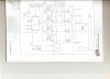
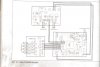
I think it is very interesting how they used the (IC4) ICL7665S (Over / Under Voltage Detector) for Anti-Islanding. I think, the OUT1 / OUT2 line pulses low for a portion of each and every half cycle with very specific timing to prove that a reasonably good AC Sine Wave with the proper Voltage and Frequency from the Grid still exists. Possibly, this Inverter is shut down if the Voltage and/or Frequency are not within spec's.

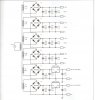
This appears to be a PWM Inverter so it should make a reasonably good sine wave.

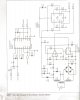
The circuit for IC4 was "lifted" directly from the Intersil Data Sheet (fig 12 - Single Supply Fault Monitor) but is used here to monitor the Semi-Smoothed Half Wave signal on C12/C13.

If another Pure Sine Wave Inverter or Generator made a "good-enough" sine wave, I think, this Anti-Islanding circuit would keep this Grid-Tie Inverter online. I think that is OK.

Circuit Errors in Anti-Island Circuit ...
1) R20 / R21 / R22 are missing a connection dot.
2) R23 / R24 / R25 are missing a connection dot.
3) G8 L7805 is missing a ground connection symbol.

Also, I think the Zero-Cross detector can also stop this Grid Tie Inverter when the AC Grid is down.
 
Last edited:
There's no need for a small grid tie inverter to be so complex! :eek:

I did a complete inverter project that just needs an 8pin PIC and 2 FETs, see this thread;
Tiny Sinewave inverter using 8pin PIC
**broken link removed**

To turn that into a grid-tie, all it needs is one simple and reliable system to detect mains edge, that will be used for synchronising the inverter to the mains and also to ensure the inverter will shut down if the mains edge does not occur.

It would only need minor additions to my Sinewave Inverter software to add an optocoupler to do the mains edge detect.

On the same page there is another circuit that synchronises to the mains edge, which is used to generate 60Hz from 50Hz but with minor changes it could easily synchronise 60Hz to 60Hz with the phase angle you desire etc.
 
Status
Not open for further replies.

Latest threads

New Articles From Microcontroller Tips

Back
Top