Continue to Site

Welcome to our site!

Electro Tech is an online community (with over 170,000 members) who enjoy talking about and building electronic circuits, projects and gadgets. To participate you need to register. Registration is free. Click here to register now.

  • Welcome to our site! Electro Tech is an online community (with over 170,000 members) who enjoy talking about and building electronic circuits, projects and gadgets. To participate you need to register. Registration is free. Click here to register now.

Grid Tie Inverter Schematic

Status
Not open for further replies.
Exactly! Once you know the basics its just a matter of a few added details to make almost any stand alone inverter system grid tie capable with in reason.;)

Add the proper synchronizing circuits, some basic safety interlocks, and some filters if needed and thats really about all there is to it. :)
 
This may be record for longest thread.

My 2 cents.

A low freq transformer can double as a choke to filter out high frequency PWM drive. Several sinewave inverters on market use this method, although there is some sophistication on core alloy selection and useable freq delta between PWM rate and 60 Hz output.

When driving high power push-pull transformer with PWM there is an issue with potential D.C. bias of transformer core caused by mismatch on drive between sides that can saturate or at least take significant range out of core material. Notice there is a capacitor in Freescale block diagram although this method is not too practical. Most of the commerial inverters have an extra circuit that detects and zeros out the imbalance by slightly adjusting the PWM timing.

For GTI, a common method for detecting valid grid is wobbling phase of inverter slightly and seeing how inverter current reacts to measure effective impedance of grid.

PV panels require a smooth d.c. load to operate efficiently and for MPPT controller to work correctly. There has to be a sizeable storage element (capacitor) to smooth out the 120 Hz sinusoidal power pulses pushed into the grid. This is easiest done at the boosted D.C. point since this is where ripple voltage is best tolerated and corrected out by A.C. PWM conversion. Don't use electrolytics at this point though as they don't like ripple voltage. Doing it at panel requires a very very large capacitor.

I have never seen an open ended 'E' core used like the boost inductor in the earlier post. How do you say 'leakage inductance'! I bet every wire within a two foot radius is getting the inductor's waveforms induced in it.

If you build and install one on your own and for some other reason your house burns down you might find your insurance company will not cover you. Some power companies will disconnect your power if they find out you have a non-permitted and non-approved installation.
 
17 pages isn't even close to the record.
 
So what is the longest official thread?

But pushing 49000 views in one year is rather fair numbers though! :)

I still wonder some times if its not just the same 490 people who have read it about a 100 times each because my writing skills where a bit rough at the time I wrote it and they just cant make heads or tails of it! :eek:

I wonder how many GTI's there are now for 'senior projects' as well? ;)
 
Attached file is Voltage curve and Current curve of circuit I posted in#235
Specification for this grid tie inverter is
-DC bus voltage 70-130V
-Output voltage 220Vac
-Output Power 1000W
-Power factor >0.95
-Total harmonic Distortion <2%
 

Attachments

  • Output.jpg
    Output.jpg
    74.6 KB · Views: 1,517
  • harmonic.jpg
    harmonic.jpg
    56 KB · Views: 1,293
Hi GRID TIE INVERTER SCHEMATIC

I was wondering if someone could put the grid tie Inverter schematic in simpler terms so I could build one for use at my house ?
 
For those of you who have followed this thread to its likely end now I have a new thread that is a more advanced continuation on the original concept of having a home built GTI device that can be built by the average electronics person on the cheap using common parts and materials. :)

https://www.electro-tech-online.com/threads/grid-tie-inverter-schematic-2-0.105324/

Just for posterity this thread was at a view count of 66,809 as I wrote this on March 27 2010!:D

Who knew hack writing could go so far. :p
 
Much easier. Made is simply a grid tie inverter. Here is no a full bridge(4 transistors) like above is shown.
 

Attachments

  • grid tie.JPG
    grid tie.JPG
    34.5 KB · Views: 1,273
you can pick GTI up on ebay now for as little as £ 80, are they likely to be any good ? I think again there will be the problem in the UK of the electric board approving of them
 
Dvinchy, that's not a schematic, it's a block diagram with no component values nothing practical can be made from the image.
 
Last edited:
Put a diode in the DC side so it cant feed power back to its DC source and that is about as simple of conceptual GTI as you can get. ;)

Unfortunately you are late for the party. This basic design concept was mentioned in my first post here, # 31, over a year ago and rough schematic for it was posted by Jules Theone in post 34. :)
 
The main transformer 12-24-36-48.../230 (its depending of requirement). The control transformer is in range 220/6X2(1-2 VA). Couple of MOSFET IRF-1010. That is all
 
Last edited:
"Put a diode in the DC side so it cant feed power back to its DC source and that is about as simple of conceptual GTI as you can get."

You are absolutely right. Here it is...
 

Attachments

  • grid tie.JPG
    grid tie.JPG
    35.3 KB · Views: 2,242
There you go! :)

Size your switching devices for 4x the input current and 10x the input voltage and your good to go!
But keep the overall power levels down. This design has horrible line harmonics and is naturally unstable at any higher input power level or voltages.
Typically Under 100 - 200 watts and around 20 volts or less input is about all these can do before the switching spikes and losses pop the switching devices or line noise on the AC side starts getting real bad. :(

At least you are thinking about the concept! :D

Now put a bullet in this thread before it starts to grow again. :rolleyes:
 
power factor correction

What a treasure trove of info on this thread. I am very curious about one aspect, how does someone do dynamic power factor correction on the AC side. The only idea that comes to my mind is a bank of capacitors with EM relays operated by GPIOs from a up based on the difference in phase measured between the current and voltage. Any other better ideas ?
 
What a treasure trove of info on this thread. I am very curious about one aspect, how does someone do dynamic power factor correction on the AC side. The only idea that comes to my mind is a bank of capacitors with EM relays operated by GPIOs from a up based on the difference in phase measured between the current and voltage. Any other better ideas ?

Do you have a single AC circuit with a number of inductive loads that turn on and off? What we are doing is PFC for each load, the caps are not that expensive. Can you give more information, such as 3 phase, 1 phase. Is this a home or commercial application? Where are you located?
 
Last edited:
^^^ this is for a robotics lab, we have an inverter sourcing out current to x number of motors, each one turning on and off at certain times. These are 3-ph motors and our inverter is also 3-ph. Btw, this is the inverter that i built along with my colleagues sometime ago. So now we see that in the worst case the power factor is really bad when a large number of motors are on. We explored some options to correct power like low val caps based on the minimum number of motors that would be on at any point but that took us only a little further. Any help in this matter would be appreciated.
 
Grid Tie Inverter 2.0 has been updated again with new schematics and revised control circuit designs. ;)

01/12/2011 For reference this thread is now approaching 113000 views! :D
 
Grid Tie

Hello.
I'm from Poland, so sorry for grammatical errors. My English is not very good.
I have a wind power plants with a capacity of 1kW at 24V. I have control made ​​by me (www.wintechenerg.com). All the power is usin 'for charging. At present, the technical condition of the batteries is disappointing, therefore, I want to do the layout of the transmitting power to the grid.
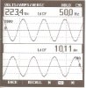
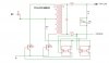
I made the system according to the attachment, and I have a serious problem. Once connected to the transistors, into a zero crossing, I have all the time short circuit.
The system, instead of giving energy, gets a lot more when you connect to the installation of a windmill. Transistors strongly heat.
After a few attempts to opto-isolator system has been destroyed, so plugged into the control voltage transistors from a different transformer connections. It has two windings 15V and also 9V. I just used a 9V to control.
Please inform me whether in this form, the system connected to a wind turbine should be working properly?
Dvinchy posted schematic, but the effect is the same.
 

Attachments

  • untitled111.JPG
    untitled111.JPG
    27.7 KB · Views: 1,223
Regards from Poland.
Try to use concept posted by TCMTECH. In His idea U can adjust zero crossing dead band, and idea is not to complex.
In Your concept the Zero Crossing Dead Band is constant, and depend on optocoupler gain, optocoupler diode volt-drop, and few elementary things only!
U can not adjust zero crossing dead band in You concept. Still current in transistors strongly depend on zero crossing dead band - as TCMTECH describe already. The only way to limit current in transistor is switching it on, but not too soon.

Smoku74 / Dragon74
 
Last edited:
Status
Not open for further replies.

Latest threads

New Articles From Microcontroller Tips

Back
Top