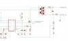
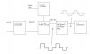
Hi! I got interested as I'm thinking of building one myself, otherwise I won't graduate next semester. LoL. My idea is to build an H-bridge with the high side switches connecting at 60 Hz (it's 60 Hz here) and the low side ones running at high freq SPWM as Hero suggested.
The current harmonics will be filtered out by a low value sense inductor in series with the line. The focus of my project is proper timing of the control switches.
The problems I've encountered with the design so far are
1. getting proper line voltage feedback (I believe an unknown value lag would come from feeding back using a transformer)
2. I'm thinking of using FET switches with snubbers. With a DC current source feeding current into the H-bridge, overlap times would be necessary otherwise, there would be no path for the current, right? Following this argument, how will the SPWM scheme (requires off times) work with a current source?
As far as I've heard, most applications nowadays use MC. I would want to make one using only analog components though.
Also, this is my first time making the circuit, so any help/criticism of the work will do. Thanks.
PS. First time joining a forum. How do I post my schematics? LoL
")