Continue to Site

Welcome to our site!

Electro Tech is an online community (with over 170,000 members) who enjoy talking about and building electronic circuits, projects and gadgets. To participate you need to register. Registration is free. Click here to register now.

  • Welcome to our site! Electro Tech is an online community (with over 170,000 members) who enjoy talking about and building electronic circuits, projects and gadgets. To participate you need to register. Registration is free. Click here to register now.

Grid Tie Inverter Schematic

Status
Not open for further replies.
For what it cost for a good grid tie inverter rated a 15kw I could power my home for 14 years
 
Perfect circuit for it! its just what I have been using for years.
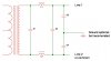
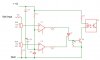
On that H bridge you should have some reversing diodes on the switches to conduct voltage backwards for when the source and drain voltage potential reverses on each alternating half of the cycle. Thats why I love IGBT's, most have a reverse diode built right in. Put a small capacitor across DC side of the H-bridge and put a diode in the 12 volt side so the power can go to the H bridge but not back to the power source and you have it!
You just have to switch the H bridge in phase with the lines and you are ready to go.

If you have been reading what I have posted about the phasing you are aware that the switches need to be off just before the wave reaches the crossing point from positive going to negative going. and back again. Basic GTI 101. I posted some basic info on control transformer selection before. It relates to turning on and off the switching cycle of each half of the wave at around 20-30 % of peak volts. Thats the dead band area to keep the switches from trying to carry theoretical infinite current as the sine wave drops to zero and produces no back emf.
Plus you can hide that pesky little phase lag problem in there too if your drive circuit is transformer based.
You dont actualy need to have the input voltage above the line voltage durring the full cycle to get goo grid feedback. If you turn your switches on at say 3 volts in referance to having a 12 volt AC power side transformer you will get a fair amp draw but it drops quickly as the wave voltage rises. As soon as the sine wave reaches your 12v input your amps are at 0. If the transformer is a 12ac its peak volts will be 16.96. That top 4.96 volts put your in that reversed state. thats why the reversing diodes are needed. and the blocking diode too, so the peaks cant dump backwards to your power source.
As the sine wave drops your switches will start conducting and the current will rise again starting from that 12v equilibrium point and keep going up untill you turn them off. hopefully around that 3 volt point. Then repeat this all again for the other half of the wave.
Factor in real life things like the winding resistance, and the counter emf produced from the 12 volts feeding into the transformer and starting the magnetic field sturation climbing faster than the sine wave coming in from the other side of the power line and you have a basic current limiter built right in.
No high speed PWM wave form shaping required. Just move your on/off switching points higher or lower in reference to the 12 vac sine wave!
Put the right size power factor correction capacitor on the line side, feed the power through a basic LC tank filter from a power supply of similar wattage and voltage and you have clean Ac going backwards! no harmonics and line hash!

Before anyone jumps all over me with their Mathamatical Monkey Poo relating to theoretical harmonics and line spiking stuff, build it and run it with a O-scope and a spectrum ANNALizer on the line side.
Then tell me where you see all that stuff! I still cant see it on mine.
Bet that iron core transformer and power factor correction capacitor make a real good LC tank and filter that loves 60 hz and not any other frequency! Plus that small inline filter takes the high frequency stuff and knocks it down if there is any.
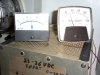
Put the O-Scope and spectrum ANNALizer on the switch side, then I will happily agree with all that MMP! Good chance you will see all the stuff you are so worried about. I know its there I can easily see it on my O-scope. The switch side is a messy sort of square wave shape! Line side is a good normal sine wave!
Unless you are really pounding on that transformer with excesive input volts and amps. But then you will pay for it! you will be grossly over driving the VA limit of the transformer and then here comes the smoke!

15 KW factory.
Yea, I could run my house for about a decade for what they cost too.
Home built thats more in the 15-20 cents a watt range. If your good at hunting for those parts from used commercial devices.
My local scrap yard gets transformers from time to time and they sell them at used electric motor price. about 55 cents a pound. my 15 kva 120/240 : 240/480 was about $220. It was a little dirty and roughed up but high potted good and no bad hum when its powered up.
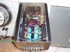
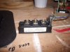
Massive IGBT's, 1200 volt 600 amp are $25 to $100 on eBay for good used or new old stock. but availabliity varies. I paid $160 for 4 plus shipping of course, last summer for that size of toshiba IGBT's.
My control system is a Teco PLC system. New at B&B electronics for under $200. Software is free online at their website.
Check it out you can start writing your own control programs before you ever get the controller or the GTI built!
Now does 15KW sound like its more in a sane persons price range?
 
Last edited:
Some of you are wondering about me by now. How can I do this sort of stuff legally? Well location is everything! I live in rural North Dakota that’s why. Its legal in my state to back feed up to 50 Kw an hour and get full price for it credited to my meter account! Unless they changed that and I nave not found out about it yet.
How can I be connecting to the grid with a big home made unit? Well I do have to have my utility company engineers check it over first. Unlike most of the power companies mine is customer owned, not corporate owned. I have super people to work with!
My cooperative is pushing to be one of the few in the country that is customer owned and have its own wind generators to save the customer money not to make more for some corporate group. So that’s why I am confident they will Okay my system. It’s great PR for the both of us. And being my design if something is not good enough I can just change it to suite what they want.
How am I going to get a way witha15 Kw of wind generators on my property? Simple I live out in the country and my nearest neighbor is a ¼ mile away. And the basic zoning law here is if your neighbors say it’s Okay, then you can do it. I love my neighbors!
How did I learn to do this type of stuff? My business is custom commercial and industrial maintenance I specialize in electrical system and power control devices.
Plus I have worked on welders and plasma cutters for many years and am very familiar with the high power inverter power supplies they use.
It’s why I don’t get to wound up over harmonics and grid line noise. I know what a 60 Kw inverter can do, how much line noise they really do make and how that noise they make is filtered out. I work with them! If you are wondering where you find one of those monsters, check out an industrial production plasma cutter. The big production ones can easily push 300-400 volts and 200 amps at the cutting head at 100% duty cycle. That’s arc volts and amps! Throw your MMP at that and calculate the EMF and RFI potential spewing out!
See why I don’t take harmonics and noise concerns at the test bench level to serious.
Hope this clears things up a bit more.
I am here to help and with real world experience!
 
There doing it here in Tn people are trying all kind of things water power and stem power where I worked we had a power plaint that could power are town. I have a basement full of electric parts and controller boards. You name it I have it. My best friend owns it now he gave me what ever I wanted. I'm the plaint Electrician. now I have time to play with my dreams.
 
Last edited:
Then you have access to the bigger components too! My big 15 kVA transformer came out of one of the local power plants. Along with a truck load of other things I have scavenged over the last few years.
Then you must also be familiar with what I have been saying about real world line noises and how the system tends to naturaly take care of them to a large degree.
If your at the power plant end you get to play with bigger toys than me!
But you still see how generating your own can still be a fun challenge.
Got any tips from the big end of the electrical mountain for us?
 
I thought you may want to see this
(I heard and saw the results of a
50 MW diesel genset being synched 180 degrees out as the result of
reversed leads on the synchroscope. Literally ripped the stator out
of the foundation and twisted the shaft.)
I have never tried the grid tie but I have paralleled generators for more power and the one that is bigger will synchronize the smaller generator. So any home made grid tie inverter you need to make sure it's in phase.
 
Last edited:
HaHaHa.
When I went to college my first time back in 1993 one of my professors had a video of some guys trying to do that with a PTO generator at someones farm. No breakers on a 20 KW with a 60 something hp tractor! One big switch and a drect tie to the farm main panel. Same thing Happened to them, The tractor Flipped the pto genset right over and the big power cord they had ripped their switch and meter panel right off the pole! fortunately the PTO shaft broke and the big fuse on the pole transformer popped.
No one was hurt but I bet some explaining was involved when the utlities had to replace the fuse and the panel!

IS it common sense first or saftey first?

And yes I have 180'ed my GTI experments once or twice in the begining. Thats why I also recommend the current limiter and low start up voltage method for first time run up.
 
Dumpster Diver Tip!

Got a heavy lug or large solder connection you just can’t quite heat up enough with your Buzz gun (transformer type) to get it to melt all the way?
Pull the soldering element loop off and put a large copper or brass rod or wire in each socket. Now put the two open ends onto the big solder joint and try heating it up.
You just moved your heating source from external contact to direct internal.
The joint solder resistance is generating the heat right in the joint itself!
It may be just enough to melt that solder and get that valuable thingamajig off that what ever it is.
Or you can just go get the propane torch. But what fun is that?
 
Time for some basic control circuits.

Item One: AC side connection.
The simplest way I have found to connect and disconnect to the lines is with simple solid state relays. Use ones with zero crossing not random turn on. These automatically connect when the two voltages and phases are in that zero cross band.
Simple, effective and already made for you! No complicated voltage and phase monitoring required.
(Almost painful to see how obvious that one was!)

Item Two: DC side connection.
Remember that blocking diode that keeps the H-Bridge from feeding power back to the DC source? Use an SCR with a photo coupler trigger. You now have the same control set up as the AC side. Don’t worry about the SCR latching and not turning off. If your H-Bridge is working right you will be getting several zero amp draw points each cycle. If the SCR is not constantly being retriggered it wont keep the DC source feeding in.
Now you have basic switch control over both the AC and DC sides of the system with only a few volts and milliamps required to drive them.

Item Three: Voltage sensing.
I have used a basic two step voltage monitor with great results. Use a duel op amp comparator to drive a SCR. Set up the comparators to monitor the voltage at two adjustable voltage ranges. For reference comparator 1 is the upper voltage trigger unit and comparator 2 is the lower voltage reset unit.
Here’s how it works. As the voltage you are monitoring raises comparator 2 (reset) will go high output. That powers the SCR directly. But without the gate triggered it won’t conduct yet.
As the voltage rises above comparator 1 (set) it will go high output. This triggers the SCR gate. Now the SCR is on and you have an output to drive the next stage.
As the voltage drops comparator 1 goes low output and turns off the gate drive. But the SCR is still latched and keeps the output to the next stage high. As the voltage drops Comparator 2 goes low and drops the output to the SCR. This drops the SCR output to low and turns off the signal to the next stage. That output of the SCR can drive an NPN transistor that triggers your solid state switches
Now you have a basic adjustable voltage window switch. You can use this for the DC voltage monitoring turn the system on and off automatically.
Multiple units can turn on the control transformers before the AC line connects. This way you have the power transformer up to speed before switching onto the grid.
Add another comparator circuit and use it to drive another SCR to switch The DC power onto the center tap of the power transformer first (if you have one available). Your GTI just became a two stage. Just make sure your lower voltage input( half bridge mode) is set to turn off and transfer to the higher volt (full H-Bridge mode) input at the right level and switch back when it drops low enough.

Item Four: Frequency monitoring.
Use a frequency to voltage converter of some type and have the frequency monitoring taken care of by simple voltage comparators! Frequency and AC upper and lower limits just need high limit off and low limit off not a set/reset window.

You may have some false triggering from electrical noise though. I recommend using those monitor outputs to trigger some type or delay timers to filter out miss fires. A .5 to 5 second adjustable delay before the solid state switches are turned on and off takes out a lot of the misfire problems!

And yes there are ICs that can do all of this for you too! If your aware of that then you problibly already know how to set one up.
 
Can you draw if so lets us see it most people like my self can see what your talking about better.
 
Last edited:
Sure. Ive Been working on it in my spare time. I have to learn how to use the SIMetrix first.
Its way different than what I am used to. I know what I want to do but my mouse hand thinks I am running auto cad! Plus I am still checking out the symbol libraries.
I hope I can finnaly get something out by tonight or tommorow.

Now that I have given out some basic setup hints on how to reference things for phasing and basic system monitoring anyone out there start dreaming up a way to use a microprogrammer for the control work?
If you think about the voltage referencing being taken right from the AC lines you can take out the control transformers and start going all IC on the control circuit!
Think optocouplers, comparitors, and IGBT/Fet driver IC's!
Check out that website I mentioned for data sheets in an earlier post. If you have an IC in mind they have simple application circuits with most of the data sheets.

I am not going to spoon feed this stuff but I will point and show. YOU will still have to think for yourselves! Its how I had to learn it! Your just getting the benifit of my hard learned knowledge to point you in the right directions and help you skip a few trial and error steps.
I have a whole ice cream pail of smoked ICs, mosfets, IGBT's, transistors, diodes and blown capacitors I collected over the years from failed experiments.

I am pointing out the better paths to take but YOU still have to walk them!
 
here is the basic but reliable H-bridge design.

Okay use your imagination. I cant get this image to transfer.
Is there a simple way to cut and paiste here?
I could use some help!
 
Last edited:
Click on "POST REPLY" and scroll down to "manage attachments"
It will let you browse & upload your files.
 
Last edited:
After much file format change attempts and some trial and error here is the actual H-bridge and DC input circuit!
 

Attachments

  • Basic  GTI.jpg
    Basic GTI.jpg
    53.8 KB · Views: 2,378
Last edited:
And heres the basic AC side.
 

Attachments

  • Basic  GTI  AC side.jpg
    Basic GTI AC side.jpg
    47.8 KB · Views: 2,713
Actual home built GTI

And here is my actual 900 watt GTI with the high resolution watt meter. Set up for 10x watt reading!
Thats 5 kwh if your wondering, and thats just from wind last night!
The analog control board is under the two big blue capacitors. The AC conneting SSR is just behind the left IGBT half bridge and the DC Connection SCR is behind the right side IGBT half bridge. The power factor capacitor and line filter are behind and under the power transformer. The little black capacitor in the center is the 100 uf filter cap on the H-bridge DC side.
The big blue capacitors are not hooked up. They are glued in but dont serve a purpose any more.
Yea, the pair of 200 amp 1200 volt IGBT's are way overkill but I got them cheep and figured I would use them. ($10 each on eBay) Toshiba MG200Q2YS42 if your courious.
This unit is dual range capable. 22 - 90 volt full range or 22 to 45 volt low range as its set right now. It can handle 35 amps at 45 volts for about 2 minutes (1500 Watts) or 90 volts at 18 amps before it overheats. So I have plenty of head room for those high gusts. The top efficiency is around 80 - 85%
turn on at 22 volts gives me about 15 watts feedback, line watts not input watts. input is more like 45 watts at that level.
I built it into an old 24 volt 25 amp power supply case if your wondering what it used to be.
 

Attachments

  • DCP01311.JPG
    DCP01311.JPG
    198.5 KB · Views: 2,809
  • DCP01312.JPG
    DCP01312.JPG
    299.6 KB · Views: 2,458
  • DCP01317.JPG
    DCP01317.JPG
    239.7 KB · Views: 2,029
Last edited:
Voltage Sensing Deadband Switch

Heres the Basic Voltage Sensing Deadband Switch.
 

Attachments

  • Basic deadband voltage sensing switch.jpg
    Basic deadband voltage sensing switch.jpg
    45.4 KB · Views: 2,589
I think i found what I need I have 6 of them there 30 amp 1000volt half H-bridges QM30DV-2H I played with it last night I stepped my 12 volts up to 240
but it was still a square wave
 

Attachments

  • GEDC0328.JPG
    GEDC0328.JPG
    41.2 KB · Views: 2,604
Super!
Being current controled if you are using a transformer drive system for the time being you may need to add a few diodes in series with the base input to increase the turn on voltage point. And dont for get the current limiting resistors on the base input! The specs on the QM30DV do show a base to emiter voltage of 3.5 so you already may be good to go if you are using a 10 -12 volt AC control transformer.

If you use the 6 together (3 on each leg) I would a expect it could run at 15-20 amps Ave input current and probibly a fair amount more!
And possibly up to 500 volts DC input!
(If you have the right size capacitor on the H-bridge. Plus the proper line filtering circuit of course! And obviously you are using a 240 Volt AC transformer not a 12 volt!
That just theoretical, Actual real life often proves different.)
 
Status
Not open for further replies.

Latest threads

New Articles From Microcontroller Tips

Back
Top