Continue to Site

Welcome to our site!

Electro Tech is an online community (with over 170,000 members) who enjoy talking about and building electronic circuits, projects and gadgets. To participate you need to register. Registration is free. Click here to register now.

  • Welcome to our site! Electro Tech is an online community (with over 170,000 members) who enjoy talking about and building electronic circuits, projects and gadgets. To participate you need to register. Registration is free. Click here to register now.

Grid Tie Inverter Schematic

Status
Not open for further replies.
Thanks tcmtech,

this was all possible because of your inputs. I'm planning to build a small system with 200-300W solar panels, probably buying them from ebay. It's for our house in the UK. As electricity companies keep charging us to death, this the least we can do. Apparently there are new panels out which can be 18 pc efficient.
When you want to center-tap-earth the output using 2 capacitors, what value would you choose? I tried high and low ones. The trace becomes cleaner and more rounded with the higher ones (5u, 0.33u, 0.1u, 10n, 220p). Is there formula or rule-of thumb for this?

thanks,
selim
 
Basically just keep experimenting like you did with the output capacitors until you find a point where you're happy with the output waveform.

I am guessing that given your size of system that 5 uf is going to be about right.

If you can see it's rounding off the waveform a bit and canceling out any visible harmonics ticks on your Oscope it's close enough.

It's not intended to be a high precision waveform shaping and filtering circuit.
 
Hi Fendel,

this looks really interesting. I assume you'd need a big DC source to alternate and upload to the grid. I'm not familiar with DC SSRs. If they act like a switch, conducting current in both ways, this could work. Are they fast in switching?

In fact, if you have, let's say 600VDC, you could go transformer less using HERIC with an output of 220VAC RMS.

tcmtech posted a really good document regarding Heric a week ago.

there is german youtube about heric, the guy who achieved 99 pc on
https://www.youtube.com/watch?v=036Xwz_vEPc

The culprit is called Blindstrom (german)=blind current, which is responsible for performance degradation, flowing opposite the working current in regular GTIs using PWM.

just watch the animation from 2:25-3:18

have a look at the Morris pdf as well.


ps can you make another drawing? thanks

regards,
selim


Hi Selimy and tcmtech

I use 4 solid state relays 40 A, 5 to 220Vdc, command 3 to 32 Vdc, and I want conect them direct on the 220 Vac grid... without transformers...
 

Attachments

  • Morris_2009.pdf
    1.8 MB · Views: 1,165
I use 4 solid state relays 40 A, 5 to 220Vdc, command 3 to 32 Vdc, and I want conect them direct on the 220 Vac grid... without transformers...

I have doubts that those types of SSR's will have fast enough turn on and turn off speeds to keep the switching points in phase with the primary wave form plus your 220 VAC power has a peak voltage of around 310 volts which is way past your 220 VDC SSR's ratings.

If you have ever read my posts you would know I don't recommend using switching devices with voltage ratings of anything less than 2X the peak AC voltage which in your case would put the minimum I would go with to be around 600 VDC!
 
Hi, the normal China DC SSRs I buid, are very fast at low comand voltages, altoght in there folder there specifie lower velocities...
I think I read all treads off tcmtech, in multiple titles, and I forgot the minimum 2x peac Ac voltage rule, because I also forgot that the SSRs are DC, and not AC...
I dont verified if my SSRs are still good after the fuse blows, I dont make other more tests.
I speak an read german very vell, much better than englisch, hehehe.
Before the fuse blows, also before I conect the output to de grid, I make very good osciloscope square figures at 60 Hz, and as I vary the potenciometer, the lenght off the rectangular waves varies also, in both ends (begining and end) and if there are to high comand voltages, I fell they tried to oversnap the rectangles, that I dont can see at the osciloscope, but the imput DC current increases, without injecting any energy.
To respect the 2x rule... I will trie to repeat the next tests connected at a 110 Vac transformer... but before that, i think it is good to put some aditional break schwith in some place...

Yes I will make a new drawing tomorrow...
 
Last edited:
gti esquema ssr.JPG

thats the remake drawing...
 
Hı Fendel, thanks. Really clever idea. I put it on iCircuit and it worked using 2 relays.

The way the other 2 relays were connected caused shorts, maybe iPad's not fast enough in switching.

I used regular relays as the Ssr part in i Circuit is not available.

If your Ssr s are fast in switching and have the higher voltage capacity it should work. Would be interesting to find out it's efficiency.

regards,
selim
 

Attachments

  • image.jpg
    image.jpg
    557.6 KB · Views: 1,161
Hi Semily,
The potentiometer regulates the imput SSR comand voltage, and the SSRs needs a minimum command voltage to switsch. So, with the potentiometer we can regulate very nice the time the SSR schwitches... on and off, at almost the same minimum voltage.
It function very nice at very low command voltages, near of 3 Vdc...because these operating voltage is achieved only for schort time of the 50 or 60 Hz wave... and so, that time we can regulate very easy with the potentiometer.
Realy for higher command voltages, above perhaps 5 volt (dont remember the values) ocur a schort, because the rectangular waves plus and minus interscect one with other.
So, in your iCircuit you can trie to put some variable schwitsching time retardants on the command on and off voltage...
Tomorrow I go travel, and come back at saturday, and still not know if I connect email in that time.
Meanwile e read part of your recomendations and see H5 and Heric... and also they speak about a H bridge without PWM and transformator...
The mentioned stupid harmonic rules in so litle aplications, are tipical for nonsense doctors.
 
I am pretty sure his design will work to some effect however going by what I can find for DC SSR's of his ratings a IC and dedicated switching device based circuit using a high/low side gate drive IC and some IGBTs, Mosfets, or high gain transistors would be cheaper and more efficient plus not have near the voltage and current limitations either.

But I do have to admit he does show that very basic but still functional grid tie is not all that hard to do! :D
 
Hi tcmtech
As the energy from a wind generator varies with the cube from wind speed, I want make a litle GTI that inject energy at a great DC voltage variation, for example, from 5 Vdc to 50 Vdc, at 5 Vdc 5 W and at 50 Vdc 2 kW and 110 or 220 Vca and 60 Hz.
The higher the Vdc, higher the rectangular of a square wave. So we can inject a low Vdc just at the beguining of a higher voltage senoid curve, for a very schort time, and obtain a smal power injection. As the height of the rectangle increases (also the DC voltage) the power increases also very fast.
So, I need a circuit to command the igbts or mosfets, rectangularly, fast, just at the begining and end of the senoid half curves.
As the schort time AC sinus voltages are higher as the DC rectangular voltages, the series diodes dont let the current flow rewards...
I dont know how to make that fast and simple command circuit. Have you any sugestion?
That is the reason because I tried the SSRs.
Best thanks.
 
use a boost converter to take the 5-50 vdc and change that to 400 vdc.

flyback or tapped inductor topology is probably the best thing to use.

as to driving the grid.. i've been penciling the schematic out and i think the simplest way is to build your own pwm generator.

use a the vco from a pll, a 4046 or something similar to get your pwm frequency. (it needs to vary +/-20%) -square wave, 10v output.
change the square wave to a trianglar wave using an RC integrator, on the order of 2 volts peak to peak.
feed this into two opamps.
feed the grid's sine wave into those two opamps as well, on the order of 2 volts peak to peak

you'll get two pwm pulses out of these two opamps, configure the inputs such that they oppose each other.
to change the range of pwm from say 20% to 80% to 30% to 70% you change the frequency of the square wave (because the RC integrator output is frequency dependant.

then feed the two pwm signals into two half bride drivers, and drive your IGBTs, Mosfets, transistors, or whatever.

to prevent any dc on the output, you will need ensure that the half bridge drivers have exactly the same amount of deadtime, and the opamps have a low offset voltage.

if you want to ensure the power flow is unidirectional, set the pwm frequency so the ac voltage is a nominal value,
and regulate the power flow by configureing the boost converter for constant current, rather than constant voltage output.
 
Regarding the last two posts both subjects have been covered in some detail as to the how whys and why it is or isn't worth the effort of the concepts.

You just have to do your reading and filter out all the bickering and irrelevant posts to get to it.:p

I recommend copying all the GTI threads to a word program then just go through and scrub out everything that doesn't relate to GTI tech info.;)
 
Hi Fendel, sorry for the late reply. I found this on youtube, I think it's Italian and they use a high voltage h-brigde wo/transformer but with PWM.

https://www.youtube.com/watch?v=9x_mQip8Sl4 and the discussion and schematics are here **broken link removed**

I more or less could follow only the idea. I found this interesting as they used only one IGBT to drive the high voltage bit. Not very clear how it works I admit.

For your SSRs the iCircuit is not really the best simulator. It barely simulates relays and at very slow speeds.

A question for tcmtech?

I am very close to finish the circuit board. I have selected fast and reliable components and the output looks very stable. Before trying to upload the power I connected a 35W/220V halogen bulb in series to the output transformer (350W) and confirmed the correct phase. The bulb only had a very slight and faint glow. When I reversed the connection it was full bright and even got brighter as I increased the DC input.

While trying to upload power to the grid with the correct (in phase) connection I noticed that even when I increased the input DC slowly to 24V, the Amps remained 0 throughout, in other words, no-uploading took place.
I remember when people connected their GTIs on youtube, they first connected the DC-source (PV-panels) to the GTI box and then they plugged it in to the mains. I must have missed something here, any ideas? Would I need a small dummy load to kick start the mosfets, and if, how?

Btw, I have not center-tapped the Transformer-output with capacitors to the earth as the RCD-CB tripped on the slightest current leak between earth and neutral.

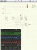
Another idea that came up was to clean the grid signal before generating dead-banded-square signals needed by the 2113s. A sort of filter, either before the primary coil or after secondary coil of the signal transformer, like a low-pass filter. Would this introduce time lag or phase shift or cause any other headaches?
 
Hi Johansen, have you got a schematic for this. I had a look at SG3525 which seems to have it all packed in. I also looked at 8038 to generate triangle shapes. One thing I had problems with was, how do you add dead band into a PWM signal?
 
Which schematic are you using and what is your transformers voltage rating on the low voltage side?

Just going by a rough guess for a 350 VA transformer to work at full output the input winding would need to be around ~16 volts AC open circuit.

Yes filtering your timing signal will likely cause some phase shifting issues. Normally it's not a needed process being that once the normal AC has passed through a transformer most of the little spikes and whatnot are attenuated far enough to not cause any issues.

Also the voltage reference to the sine wave used to produce the deadband tends to makes it so that any line noise above that switching point simply gets ignored. Also when the deadband reference voltage is below that point any spikes are fighting a near dead short equivalent of the whole power system which means that they would have a very hard time making it past the signal transformer and into the switching circuits.
 
Last edited:
Hi Tcmtech,

the output transformer is a toroidal core rated at 350VA. Input 2x12vAC (1-2ohms total when connected as 24VAC), output 1x220VAC. When I inject 24VDC from the bench power supply, I get 440VACpp quasi-square output (with aprrox. 1ms of dead band each side of the square). Efficiency: I plugged in one 35W Halogen spot light into the grid for comparing brightness and heat, and one to the output transformer drawing 24.4 DC at 1.45A (35.28W at 440VACpp). They both have the same intesity. I agree, the power factor on the gti might be slighty less, but the efficiency looks OK.

I think when I try to upload, the grid overpowers the output transformers mosfet side. and the IR2113 latch locks (Vs) to avoid possible problems.

Next thing, I will try to run the GTI with center tapped earth and a small load, then plug it in to mains. See how this goes.
 
I see now. With a 24 VAC transformer your peak voltage will be around 34 volts so to get full power feedback you would need to have a power source of around 36 volts DC or slightly higher.


At 24 VDC input if the deadband is not set too wide you should be getting a slight amount of loading going on.

If you change your transformer over to the 12 VAC connections and bring your DC voltage up what does it do then?

If it's feeding back properly at that point a little cheating on the deadband should be able to let you cheat the feedback power to match your 24 VDC input at the transformers full VA rating without problems provided your switching devices can handle the higher peak amps.
 
Thanks for your good advise, Tcmtech.

I now know what I'll do next. I will hook up the output TR to 220VAC and exactly measure the Volts on the 12/24VAC side. As you mentioned, it will be probably around 34-36VAC when the coils are connected in series, and probably around 19VAC when they're connected parallel. I will adjust its input VDC accordingly. The new MOSFETs can handle up to 65V and 60A, they're really fast and barely get warm.

What would you choose as input-power? high Voltage/low Amp OR low Voltage / high Amp DC.

Like, I could connect both 12VAC coils in parallel and inject roughly double the Amps at, lets say 19VDC

I've seen a guy on , yes you've guessed it, youtube, who've achieved better efficiency at lower input Volts (12VDC was better than 24VDC). Well, this could be device-specific? ! think, as higher volts/lower amps is put in, this should cause less heat loss and have better TR efficiency, but am not sure about the switching losses caused by Mosfets gate-rise and fall times at higher voltage.
 
Yes, got the numbers:
(Vpp measured with oscilloscope and Vac with Voltmeter)

This is what I get when 220VAC is connected to TR.
sec. coil Orange-Yellow only:
36.17 VACpp / 12.36 VACrms

sec. coil Black-Red only:
36.17 VACpp / 12.36 VACrms

sec. coils paralled Orange/Black - Yellow/Red:
36.17 VACpp / 12.36 VACrms

sec. coils connected in series Orange - (Yellow/Black) - Red, measured at Orange - Red:
71.53 VACpp / 24.74 VACrms


If connected in series, I would need to supply 35.77 VDC at max 9.78A and
if connected in parallel, I'd need 18.09 VDC at max 19.35A to stay below 350 Watts.

So 24.4 Vdc was roughly 1/3 short of what was needed. So the grid won..
 
Last edited:
Status
Not open for further replies.

Latest threads

New Articles From Microcontroller Tips

Back
Top