Continue to Site

Welcome to our site!

Electro Tech is an online community (with over 170,000 members) who enjoy talking about and building electronic circuits, projects and gadgets. To participate you need to register. Registration is free. Click here to register now.

  • Welcome to our site! Electro Tech is an online community (with over 170,000 members) who enjoy talking about and building electronic circuits, projects and gadgets. To participate you need to register. Registration is free. Click here to register now.

Grid Tie Inverter Schematic 2.0

Status
Not open for further replies.
I will see about getting a new schematic drawn up on my computer in the next few weeks. The origional one was lost when a hard drive went out last summer and it was one of a handful of files I didn't realize I had no redundant back ups of.
 
I fail to understand one thing when it comes to Grid tie inverters. If say my DC panels output 2kw via the GT inverter and my current load is only 1.2kw how does the inverter know that it can feedback 0.8kw back to the grid ?

tcmtech can we use a signalling transformer like the dst-4-16 in the control circuit b ?
 
In a way think of it as a pipe that supply's 2000 gallons of water every hour into a tank and a pump is drawing 1200 gallons an hour out of it. That still leaves 800 gallons per hour of incoming flow remaining to go someplace else. A GTI is sort of like a spillway that only gets whats left that is available as over flow. Its a somewhat poor analogy but thats the simplest way I can explain it.

The actual power limiting in the GTI is related to the zero cross dead band and the difference in the input voltage Vs the peak voltage of the grid. The difference between the input voltage and the peak voltage works to reduce the effective conduction time of each half of the cycle basicaly creating a PWM effect. The lower the input voltage the shorter the PWM duty cycle and thus the less power transfered which if everything is balance properly tends to create a natural proportional power regulation feedback loop that is controled from the available input power.

tcmtech can we use a signaling transformer like the dst-4-16 in the control circuit b ?

I assume you are referring to TX1 in the control circuit A schematic being that I do not have a control circuit B posted as of yet?

If its output voltages are close and it can supply the necessary power that the control systems use then yes it should work just fine. This design is very forgiving to slight variations in the individual components so just as long as the voltages and power requirements are met it should work fine.
 
Thanks TCM that answers my question. One more question that i have, I think the output of the Grid tie inverter and the AC mains feed into the main junction box and there on to the domestic loads. I have always wondered how the inverter power is used up first and then priority is given to the power from the mains. For example I have a 2kw system and it feeds power to the home loads, what is there in the junction box that says use up the 2kw coming in from the inverter and if you still need more power draw it from the mains, and all this when theinverter produces the same voltage as the mains. How does this happen ?
 
A GTI is in effect trying to push the line voltage and frequency higher that where it normally is in order to create the feedback effect. Being the closer of the two power sources for the loads it gets its power consumed first and what ever it cant produce gets pulled off the mains supply.

The simplest way to think of it is to equate the GTI unit to being a generator of sorts with limited power output and the mains source as being a incredibly large AC battery. If the generator is producing more power that the local loads take the excess goes to charging the battery by going backward through the power meter and if its output is less than what the local loads take then power gets drawn forward through the power meter from the mains.

Thats basically all thats being done but being its an alternating current instead of a direct current the process of creating the power and keeping it synchronized to the proper frequency and phase angles to make the power go the right way becomes more complicated.
 
After much too long of delay here is the Control circuit B schematics and writeup along with the revised, and hopefully corrected, Control Circuit A and power Circuit as well. :)


Control Circuit B

This is the basic stripped down version of the voltage and frequency monitoring circuits that only handle basic over and under frequency protection and over and under line voltage protection but does at least include an automatic line fault reset.

2 Kw Home GTI  Control system B.png

Over/under Frequency detection.
U1 is a standard LM2907 frequency to voltage converter IC set up to produce an approximate 1 volt per 20 Hz output. C1, R1, and C2 set the frequency range. See LM2907/LM2917 data sheet for exact values and tips for details on specific values for the line frequency of your application. In this circuit its receives its input signal from line (L) which is connected to control transformer TX1 in control circuit 'A' via D8 and D9. This half bridge produces an output frequency that is 2X the line frequency. Line (L) is also the reference point for the line voltage sensing circuit that is connected through D1 and filtered by C6. The output of U1 is fed to two 10K potentiometers that serve as the adjustable voltage dividers for the high and low limit frequency limit detection circuit which is composed of 2 of 4 op amp comparators in the LM324 quad op amp IC. The operating principal behind this dual comparator circuit is that one is set up with an inverting output and the other is a non inverting output. The low frequency limit is set up with the no inverting output so that if the input frequency is above the minimum set point the output is held in a high state. The high frequency limit is set up with an inverting output so that the output is held high until the high limit is reached where it then switches to a low output state. The purpose of these two op amps being held high in normal working condition is to allow the U2 LM555 output to remain in a low state completing the circuit for the SSR that controls the main power transformers connections with the main lines and to keep the shutdown pins of the IR2113 IC’s held low. This control circuits upper and lower limits should be set to around +- 5% of the mains frequency.

Over/under line voltage detection.
The output of D8 and D9 of control circuit ‘A’ line (L) is also fed to two more 10K potentiometers through D8 that serve as the adjustable voltage dividers for the high and low limit line voltage detection circuit. This circuit is composed of the other 2 of the 4 Op amp comparators in the LM324 quad op amp IC. The operating principal behind this dual comparator circuit is the same and the one for the frequency over/under circuit set up with one working as an inverting output and the other working as a non inverting output. The low line voltage limit is set up with the non inverting output so that if the input voltage is above the minimum set point the output is held in a high state. The high line voltage limit is set up with an inverting output so that the output is held high until the high limit is reached where it then switches to a low output state. This setting should be set to approximately +- 10% of the primary power lines rated voltage. The purpose of these two op amps being held high in normal working condition is to also allow the U2 LM555 output to remain in its normally low output state as mentioned earlier.

Fault trip and reset timing.
This circuit is based on a common 555 timer IC working as a delay timer with adjustable times for both the rise time and fall timing of the trigger and threshold inputs. The purpose of this dual time delay setup is to allow for a short duration time delay on any faults that may occur due to the line frequency or voltage going too far out of its acceptable working range. A short shutdown time delay is necessary in order for the GTI to ignore false line fault issues that are mainly due to short voltage dips caused by larger appliances and devices starting up and is controlled by VR5, R9 and C5. In a way its primary function is to work as a simple line glitch filter so that the GTI does not trip out every time there is a minor line side power issue. This setting can be anywhere from .1 to 2 seconds. The reset timing is controlled by VR6, R5, and C5 and can be set for whatever reset time delay is most convenient. Typically 3 – 5 seconds is a good starting range. By changing the values of the components here longer or shorter timing ranges are possible that are beyond the suggested ranges.

Design wise none of these values or components or circuits are set in stone so should your particular application have different common parts to work with by all means make the necessary adjustments to suit your personal application.
I included revised reprints of the power system and the Control circuit ‘A’ schematics with some slight schematic revisions to clarify particular circuits and to fix a few drafting and connection layout errors that are present in the first ones. Hopefully I have the bigger mistakes taken care of now but should you find an error in my schematics let me know or consult the IC manufactures data sheets to see if they have a more correct suggested component value or circuit layout. :)


2 Kw Home GTI Power System.png 2 Kw Home GTI  Control system A.png
 
Last edited:
Any ideas or input for my gti with your design

Hi TCM

Iv'e been keeping up with all of your different GTI designs and Iv'e been collecting my components and thought I would fill you in on my particulars since I get the Idea that you like to know numbers and details so you can learn from my project to add to your "base of knowledge".

I started out doing this with an interest in a wind turbine with a battery based system that utilizes a Prius battery pack with relay switching network that allows me to "swap the cells or modules as they are called in and out to either charge or use with an inverter to either feed back into the grid or to go through a conventional inverter to feed "dedicated" circuits in my residence as my power generating and storage capabilities will allow. I will attach a copy of my battery and charge control circuit for you to see and to give me any feed back about the approach I'm taking making this concept work.

The battery pack I have consists of 28 modules woth a voltage of 7.2 V each and a advertised rating of 6.5 Ah. the way my relay circuit works is I break them up into a pair of banks that either supply 28.8 volts for what I call the charging mode and then can be switched and reconfigured as a 57.6 v pack for feeding an inverter or maybe feeding a GTI like in your design.

My wind turbine for now is a PM delco alternator wound for 24 v with 8.5 ft diameter wind max 3 blade driving it to a 1 to 2.9 ratio which I think should allow the alternator to put out around 50 a at 28 volts. Of course I could reconfigure the batteries to all be paralleled to improve my capacity and just forget the relays but I am still in the fluid mode and will make my system to fit the technology I have available.

Eventually I would like to use PLC controls to manage the whole system with your grid tie inverter being the centerpiece I would build it around.

I'll end this for now to give you a chance to digest what I'm doing so far.

I will get into my list of Acquired goodies in my next post. I saw you had some difficulty with the wind max blades I just got mine a few weeks ago and I thought they looked good and I have hight hopes for them of course that means nothing if they don't perform. any way I was impressed with the super heavy duty hub that was included with them. I am just waiting for the snow to let up so I can put it up.
I had to make my mounting and pivot assembly to make my PMA alt work with the hub which needed a 1.25" shaft with a funky tapered shaft that I had to turn on a lathe at work. Talk about a Pain.

I'l also take a pic of that so you can see what I'm up to.


Any advice You can give is always appreciated.

Thanks

Best regards XmarkoX
 

Attachments

  • wind turbine schematic.jpg
    wind turbine schematic.jpg
    147 KB · Views: 2,599
More info for my Project

Hello again

I'm ready to give more info to add to my previous post to help with background and some questions I have. First I plan on using all of the add ons to make the GTI as safe and problem free as possible so as I'm building it, I figured having all the bells and whistles would be best.

One area I'm interested in is instrumentation for the front panel. You mentioned and I saw you had an ammeter and a volt meter on one of your units. I was wondering if you have thought about putting some of the pots for adjusting the different variables on the front panel. I was thinking maybe the zero crossing deadband adjustment and maybe a couple of LED's to show whats going on with the ssr's you are using to put the GTI online as well as something to show the Standby/Active switching points stautus. of course it would be nice to have the appropriate ammeters and volt meters that would show the minimum numbers that indicate the GTI is doing it's job. I was thinking input volts for the wind turbine. also an ammeter showing the amps going in and also one of those watt misers or whatever they call them to show the AC side performance as far as watts and w/hr info as well. Do you think adding these additional items would cause problems with the basic functioning of the circuits? I think not but I figured maybe you have thought about these things and maybe have a simple and straight answer to why or why not they would be something worth considering.
I have aquired an oscilloscope and was wondering if 20 mhz is fast enough? I think it should be but I havent done the math down to the inth degree on the whole circuit.

I also have 4 IGBTs they are N channel toshiba MG400Q1US41 rated at 1200 v and 400 A. I have a question or two about them. They Have 4 terminals on them and I can tell which of the 4 are for carrying the heavy currents but I was wondering about the emmiter terminal that has a small terminal as well as the large terminal. I am guessing the small one is for the control signal and I think I can tell how it would be done but any explanation on that would be nice just to confirm what I think I may already know. I have the data sheet on it but when they start talking about holes and electrons and parasitic junctions I get lost. HE HE Just being honest.

Also I was wondering if you have ever thought about using a variac for the power transformer. I still have some grey area about the interaction of the power transformer and I thought one with the correct va rating might be nice since it would be adjustable. I even saw one with a motor attached that looked like it could be driven to change automatically. Since I'm using a wind turbine its hard to nail down a solid voltage and really think that it's voltage is dependent on the battery voltage since it would clamp to it but still that number can be highly variable and then of course you have the whole charge control formula to deal with. I kinda like the idea of a high Amp alternator that would have built in regulation for my mill but the only problem with that would be losses sending DC all the way down the tower. I like sending the three phase AC down to a rectifier near the control panel. How do you like your Leece Neville unit?

Well I hope I haven't bored you with my ramblings but any feed back is appreciated.

Thanks
XmarkoX

P.S. on my last post I attached a schematic without any explanation. How it works is the relays are either all energized or they are all not energized. this would maybe explain how it works.
 
Nice to see someone else taking a interest/attempt at using this design.

As far as the front panel controls and indicators go what you put there is all up to you. Most of the circuits and related signals can easily be used to drive small multi ma LED's for monitoring or they could likely be tapped into with a high impedance OP amp to drive larger LED's or other things.

Relating to what you do with the design is really all up to you. I feel that I provided enough base information and robustness in the suggested design concepts that if you have any reasonable electronics and math skills you should be able to adapt this to whatever voltage and power levels you chose to.

My Leece Neville alternator based wind generator never flew. The P.O.S. windmax blades couldnt produce enough starting torque to ever get it going. Once I put them on the big Getty's DC servo motor in a direct drive setup they did put out power, about as much as a homemade wood set would make that was 2/3 their diameter, but they still flew apart anyway after a little over a month of normal use. The root broke on one blade and let it fold back into the tower and crashed the whole unit.

A 20 MHz O-scope is plenty fast enough. Most of the signals and switching devices are working at the AC line frequency anyway. If for what ever reason you added a PWM control to the switching devices you would still only be running a few KHz to 10's of KHz at most.

Regarding PLC control that is by far the most adaptable and easiest to work with relating to controlling everything. All of the voltages can be monitored by using simple resistor divider networks and any current monitoring can be done with hall effect based current sensors that put out a proportional voltage signal. Same with frequency monitoring it can either be converted to a variable voltage trough a LM2907 or similar IC or read directly by the PLC unit if it has the capability of reading a frequency input. Everything else gets controlled by the programing and is only limited by how complex you want to make it. I like simple so I keep my designs simple.

I don't know what PLC you plan on using but I have had good luck with the Teco PLR units from Industrial Communication Solutions - B&B Electronics. They give you the software free to use and they have loads of different PLR units to choose from with reasonable prices too.
 
Last edited:
Hello! First time poster. I've read the original "grid-tie inverter schematic" thread several times through, and now am reading this one.

Little info about myself: I'm a beginner electronics student (My limited experience is mostly power-related electro-mechanical work). For three years I worked as a traveling technician for one of the major multi-megawatt wind turbine manufacturers. (the BIG ones - I've climbed many 260 foot ladders.. I have worked at several of the wind farms in ND - tcmtech knows what I'm talking about) Part of technician training involved the converter portion of the turbine. Like most electronics, they are simple in theory, complex in practice. But they do use PWM to create a sine wave and sync it to the grid. Because they are industrial units, designed for rugged use, they have a wide variety of protective and control circuits (i.e.: over-current, over/under voltage, over/under frequency, power-factor, TVSS, remote-controlled power demand/limitation, etc.) that compliment the power circuits. The main switching was done using liquid-cooled IGBTS operating on 575 VAC 3-phase (newer designs used 690 VAC 3-phase). The work I did in that regard was mostly defective component troubleshooting and repair/replacement. Theoretical electronic design is not my strong suit, but I intend to change that - I quit my job to go back to school. I'm currently pursuing a B.S. in Electronics Engineering Technology, but I have only just begun (as the content of my forthcoming posts will no doubt betray - hehe).

So that may give you an idea about how little I know! :) I'm fairly strong with mechanical disciplines, and electrical (power distribution and motors), but electronics is a new field to me.

Anyway, the idea of a grid-tie inverter has been on my mind long before I read these threads, but I really didn't have a starting point until I came here. The information that tcmtech, Jules Theone, Val Gretchev, be08be, and some others have played and experimented with seems very useful. Networking is great, isn't it! : )

In the near future, I may be helping a friend install (3) 20-kW turbines on his property. He purchased them at an auction as complete units. They are a Chinese brand, and the schematics and documentation are obviously transliterated, making them somewhat difficult to understand. 135-foot towers, 3-phase generators and rotors w/blades, control electronics (yaw, shutdown, dump-load, power display), and inverters. The inverters are single-phase, though, and I'm concerned about having (3) 20-kW inverters running on the same phase, primarily because the local power company here recommends that single-phase generators be limited to 10-kW or less. I'm assuming they would prefer to have anything larger generate 3-phase (since that is what the main generation facilities (coal, natural gas, nuclear, etc) output and what the transmission, secondary, and distribution (I think?) run on) so a single-phase doesn't have an unbalanced load on it back to the grid. We haven't gotten to the point of inquiring with the utility company about how to overcome this issue, or what potential solutions exist (split the output among the phases?).

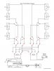
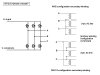
But after reading these threads, and pondering for over a month (I'm slow, ok..) I thought perhaps tcmtech's GTI 2.0 could be used in a 3-phase configuration. I drew up this crude schematic, based upon the GTI 2.0 schematic. The question I have is: would this work? From what I know, the control electronics would (in principal) be the same, gating the IGBTs based on the AC alternations, with appropriate zero-crossing dead-band delays, and protective anti-islanding, droop-frequency, voltage transient protection, etc. Of course, a 3-phase transformer would be necessary, which is essentially 3 separate transformers. I have attempted to draw the WYE/DELTA configurations in the schematic (I think they are correct - I'm not 100% sure - someone correct me if I'm wrong).

I have a feeling this would work, b/c I have seen a somewhat similar concept drawing within the technical documentation of the large frequency converters that I used to work on.

(They're called frequency converters b/c the output from the wind-turbines' generator is variable-frequency, variable-voltage AC. The converter rectifies it into DC, and PWMs it to AC. In actuality, the generators are DFIG (doubly-fed induction generators) and the stator remains a constant 60 Hz AC, while the rotor is fed with a variable slip frequency to combine with it's mechanical 'frequency' to induce an additive 60 Hz into the stator. They operate in sub-synchronous and super-synchronous mode (doesn't spend too much time at synchronous, b/c the IGBTs would be gating DC onto the rotor - almost full on/off). But anyway..

Is this possible? What other considerations need to be addressed?
 

Attachments

  • GTI2.0_3phase_concept01.jpg
    GTI2.0_3phase_concept01.jpg
    44.8 KB · Views: 2,829
Last edited:
I don't see any reason why the basic single phase design I have could not be reworked into a full three phase version. The switching control and phase reference systems would be about all that need to be added onto to drive additional switching devices for a three phase based GTI. The rest of the GTI system is fairly universal relating to what is monitored and how its handled.

I have pondered on doing a write up on a full three phase version of the 2.0 system someday but so far its a low priority.
 
Alternative to IR2113?

Is there an alternative to IR2113 which might be implemented here, since it's not available in my country at the moment.

Thanks.
 
Hi Tcmtech.

I´m following your interesting explanation about th GTI. Very good!
Can you share with us the Control Circuit C (PWM)?
Thank you for all!
 
Probably some day but I am in no hurry being that at this point if you have reasonable electronics skills you should be able to customize the circuits I have given thus far to be able to work with almost anything that works as a power source.

Besides I cant be giving away all of my secrets all at once you know. :D

(If I did then the world might not have any further interest in me.) :p
 
Ok, Tcmtech...

:)

Well... ...the project is yours. Frankly I was concerned with the description made of your GTI that has the potential to add modules. Sounds simple and didactic...

Of course I don't know how you have imagined the PWM generator. Following his idea of ​​drawing (with the use of AmpOp's and 555's), I might make would be the modulation of a triangular wave generator by the semi waves of input transformer (control circuit A)...
May be yes... Or not... :)
 
Last edited:
Thats basically how it works. Add in voltage and current limiting feedback circuits that can reduce the effective PWM and you have a basic PWM feedback regulator loop that keeps the GTI from burning out during over current or over voltage conditions on the input plus allows for a more precise fine tuning of the load VS input voltage curve peak point.

The basic circuits are similar to the way my PWM sine wave inverter circuits work for the most part by using op amp comparators to generate a basic PWM signal from an asymmetrical triangle wave.

In a way it can also be reworked to operate with a MPPT system so that if used with solar panels it can run them at their best possible power point at all times. ;)
 
I'll wait for you to show the Control Circuit C when possible, because I'm curious. In fact some years ago I did something similar in the generation of PWM for a inverter.
---
I believe there are many forum members also interested in your circuit, although they are GTI's very low cost, it is always nice when someone is willing to make public what had the capacity to do.
Can also help, if you want, drawing the PCB's for all us...
 
Hi, tcmtech. we are trying to make an H-Bridge circuit using IGBT. Our problem is that the IR2113 does not seem to be working. we already tried the configuration on the data sheet. Would you probably have a schematic of the IR2113 components you used to drive the IGBT?

Also, what is your input in the HIN and LIN? Your help would really be appreciated, thank you!
 
Hi all,

I've loved reading through all these GTI threads, and I'm keen to try a slightly different approach to one.

I have a few failed APC 1400VA UPS devices, with blown logic boards.

In each one are beautiful step-up transformers, hefty IGBT's and enough small transformers to re-purpose as control transformers.

I'm leaning towards building it as a board that's a direct replacement for the logic board that's currently in place. Simply unsolder leads, remove factory board, install GTI board, and solder on required leads.

Will be opening the case, and taking a few pictures tonight...

Nige.
 
Status
Not open for further replies.

Latest threads

New Articles From Microcontroller Tips

Back
Top