Continue to Site

Welcome to our site!

Electro Tech is an online community (with over 170,000 members) who enjoy talking about and building electronic circuits, projects and gadgets. To participate you need to register. Registration is free. Click here to register now.

  • Welcome to our site! Electro Tech is an online community (with over 170,000 members) who enjoy talking about and building electronic circuits, projects and gadgets. To participate you need to register. Registration is free. Click here to register now.

Garage door motor wiring question...

Status
Not open for further replies.

jdepaul

New Member
Hi all -

I'm new to the forum - need your help with a question about a garage door opener electric motor that I removed from the Sears Lift Master opener.

Unfortunately I did not note the wiring before I disconnected it all (initially I had no intentions of saving the motor, but then I had second thoughts).

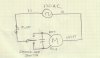
THe motor is rated at 115V - it's Chamberlain. It has three wires: white, red and blue. Connecting the power directly to white and either red or blue wires makes the motor humm, but it will not spin. I thought that maybe it needs a starting capacitor to get it going, so I hooked up the saved capacitor (230V 53-64mFd) in series with the blue wire and connected the white cable to the white lead of the power cable - it made a softer humm but still it would not start...

Measuring resistance of the three wires between the following pairs:
Blue and Red - 7.8 ohms
white and red - 3.2 ohms
white and blue - 3.2 ohms

How should these three magic wires be connected to make this motor run... :) Help me out plz -

Thanks,
James
 
Its a capacitor start/capacitor run type of motor. You need the big AC capacitor can that was mounted inside the opener.

The motor has two windings. The cap is wired in series with one of the wires to run CW and in series with one of the other wires to run CCW. I don't know the color code;maybe someone else does.
 
Its a capacitor start/capacitor run type of motor. You need the big AC capacitor can that was mounted inside the opener.
The motor has two windings. The cap is wired in series with one of the wires to run CW and in series with one of the other wires to run CCW. I don't know the color code;maybe someone else does.

Thx for your reply. Can someone help with the color coding of the wire sequence? I saved the big AC cap from the opener and that's what I used in my latest test, but like I said when I hooked up the Cap in series with the blue wire and the power lead going directly to white it only made the humm softer but it would not rotate... so I know the capacitor in series with ONE of the wires is part of the solution but not sure of the wire combination.
 
Based on the resistances, I would hook it up like this:

The no-capacitor winding has to be powered in parallel with the one that has the capacitor in series with it.
 

Attachments

  • MotorCap.jpg
    MotorCap.jpg
    240.2 KB · Views: 7,857
Last edited:
I'm with mike.As a general rule, single phase cap start/run motors have a higher impedance (resistance) on the start/auxiliary winding and a lower impedance on the run winding.The idea is to hook them both up in parallel, but with the capacitor in series with the start/auxiliary winding before the parallel connection to the common. This creates a phase shift in order create another slightly shifted magnetic field, allowing the motor to rotate, otherwise as you have already discovered, the motor will just hum, because the magnetic field is stationary. Hope this simplified explanation helps.:)
 
Mikes diagram and colours are correct for a Sears GDO motor. White is common with the colours being up and down.
As well, these motors have a built in thermal cut-out in series into the common windings
 
Last edited:
Worked!

Hooked it up last night according to the diagram from Mike - worked like a charm! Fwd and Rev - working great.

Thanks very much you all - for your advice and suggestions.

Regards,
James
 
Yes, thank you! the thread and diagram were a great help. I scavenged a GDO motor as a low speed, high torque (well, lower speed and higher torque than the fan and record player motors I've tried)
power source for a shooting gallery type automata project (chain over bike sprockets driving a couple of shafts and lantern gears)

Any clues as to what the thermal cutout time frame might be? I might be running it an hour, maybe an hour and a half. with probably another hours run time for testing. will it burn out or just shut down till it cools off? I've yanked out all the radio control and circuit boards. Its just the frame, cap, motor, plug and worm gears attached to the exterior sprocket.

Thanks for the great information here.

NN
 
I am trying to follow your drawing, the switch wiring from the capacitor to the switch, red and blue would connect to the black hot lead with the switch moving left or right for right rotation or left rotation.
 
I am trying to follow your drawing, the switch wiring from the capacitor to the switch, red and blue would connect to the black hot lead with the switch moving left or right for right rotation or left rotation.

I would say it differently; in the USA, the Black wire (120Vac power feed, L1) would connect to the common terminal of the center-off switch.
 
Based on the resistances, I would hook it up like this:

The no-capacitor winding has to be powered in parallel with the one that has the capacitor in series with it.
I'm sorry to have to ask this after you already drew up the diagram but I'm not electrically inclined and am having similar problems with the same motor.. if you can give me a picture of this same motor (3) wires - red, white and blue coming from the motor and go where into the capacitor which has 4 prongs.and from there where would they go if I had a common 2 wire plug running to a standard outlet. I don't need the technical codes or fancy arrows and and electrical terms. I need basic dummy instructions. Trying to build a Halloween prop and need to know what wires go where and which ones will make it go one direction and then the other direction. I've got the motor seperated from the capacitor and nothing in the capacitor at all. Dont feel like blowing up anything. Thank you so much.
 
Can you post a photo of the capacitor and the switch you intend to use
 
I have a westinghouse motor from a sears garage door opener, it has 4 wire, yellow, blue, red and black. I am trying to strip out all of the other componets and use the motor for forward and reverse operation run off of a manual 2 way momentary switch. I cant seem to figure out how to wire it. It doesnt' seem to have a spot for a nuetral, and i cant seem to follow the mess of wires to get it to work the way i want it to, just forward and reverse using a momentary switch. Can anyone help me?
I know it needs the capacitor that was in the power head, which were hooked up to the red and blue wires. it seem I get the same voltage on both the black and the yellow.
Thanks
 
I tried using the same Liftmaster motor to drive a meat mixer. Spent weeks tinkering on this project.

Video here:

Got everything running perfectly with no load, then added some ground meat. Start capacitor blew up after about 4 minutes under load! Black oily liquid splattered everywhere.

Surprisingly, after I let everything cool down for about 30 minutes, the motor still ran with the mixer empty. The capacitor has minor damage as shown in this photo:

https://photos.app.goo.gl/WgIQXpYgSE9cIx7Q2

You may have to zoom in to see the small cracks on top of the capacitor, near the white spot. It appears the black liquid blew out these holes, then they resealed themselves somewhat.

I'm not sure how to proceed. Any suggestions? I'd like to be able to run this thing with meat for around 10 minutes.

Thanks!
 
I seriously doubt that motor or the plastic gears will survive 10, 20, or 30 pounds of meat in that thing! Also, your air is probably only cooling the thermal switch, not the windings the switch was designed to protect. That blown start/run capacitor is trying to tell you something!
How about an old washing machine motor? ANY motor can be geared down with cheap pulleys and belts/chains. Junkyards and surplus stores have tons of that stuff.
 
Thanks for the resp0nse!

Agreed on the 10-30 lbs of meat, but I only had around 4 lbs in at the time. This motor lifted a 2-car garage door (~18 ft wide; wood; spring assisted) for 20-some years; it should be able to handle 4 lbs meat, don't you think? It doesn't require much force to crank the mixer by hand with 4 lbs meat. BTW, this opener was replaced for reasons other than the motor, so I don't think the motor is worn out.

Sure, I could use any old motor and try to gear it down, but then you're talking all kinds of BS trying to rig up brackets to hold the pullies and stuff. I really liked this garage door motor because it switches between forward and reverse easily, which is just what I need for the mixer.

Do you think the cap blew due to the windings overheating? Maybe I can try to cool the windings instead of the thermal switch...

Or did it blow from too much load on the motor?
 
It doesnt' seem to have a spot for a nuetral, and i cant seem to follow the mess of wires to get it to work the way i want it to, just forward and reverse using a momentary switch. Can anyone help me?
Do you have a picture of the motor?
 
This motor lifted a 2-car garage door (~18 ft wide; wood; spring assisted) for 20-some years; it should be able to handle 4 lbs meat, don't you think?
Your 200-400 pound door has about 200-400 pounds of spring tension helping the motor. The motor isn't actually doing very much at all.
 
AHA! I had been comparing the force required to lift the garage door with the force used to turn the mixer crank, but what I didn't realize was the mixer crank has a ~9" arm on it. I won't be able to make an 18" dia sprocket for the mixer, but I can certainly make one quite a bit bigger than I already have. That should gear down the mixer, requiring less force to turn it.
 
Status
Not open for further replies.

Latest threads

New Articles From Microcontroller Tips

Back
Top