OK, I 3D printed a new driven sprocket that is double the number of teeth of the yellow one shown in the video above. I'm hoping that gear reduction will reduce the load on the motor/capacitor.
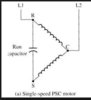
Also found replacement capacitor online for a few bucks. Why the range of Capacitance (53-64 mfd) on the start capacitor? Is one value for starting and the other for running?
If yes, would a capacitor with a higher or lower running value alleviate my problem? Which value is "running", first number or second?
")
")

