Continue to Site

Welcome to our site!

Electro Tech is an online community (with over 170,000 members) who enjoy talking about and building electronic circuits, projects and gadgets. To participate you need to register. Registration is free. Click here to register now.

  • Welcome to our site! Electro Tech is an online community (with over 170,000 members) who enjoy talking about and building electronic circuits, projects and gadgets. To participate you need to register. Registration is free. Click here to register now.

Funny problem with SPI connection

Status
Not open for further replies.

Futterama

Member
Hello forum,

I have a SPI connection between a PIC18F4620 and a ENC28J60 ethernet controller. My problem is when I read the buffer on ENC28J60. I have made a test program, that writes to all buffer locations, and then reads it back, and compares the buffer content. I get loads of errors, anything between 8000 and 12 errors while writing/reading 8192 bytes. Everything programatically works, because it has been working before.

So, I connected my 4channel digital scope, to see what was going on. Now I get no errors at all! If I then disconnect one of the probes, I get some errors, if I disconnect another probe, I get even more errors - but with all probes connected, I don't get any errors.

So I think it must be something about my SPI hardware connections.

3 probes are connected directly to the ENC28J60 Serial-In, Serial-Out and Clock-In pins. The last probe is connected near the PIC Serial-In (takes data from ENC28J60 Serial-Out).

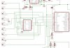
I use a 74ACT125 for translating the 3.3V Serial-Out from the ENC28J60 to the PIC 5V input. The outputs from the PIC, to the ENC28J60 is not translated since the ENC28J60 can handle 5V signals in the inputs.

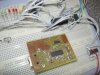
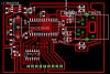
I have attached 3 images, one of the actual setup and 1 schematic and 1 board layout.

I think perhaps I need some resistors or something on the data/clock lines, but I have a hard time finding information about SPI hardware connections.

The SPI is running 6.25MHz, syncronised with the ENC28J60 clock.

Please advise :)

Regards,
Futterama
 

Attachments

  • SPI_connection.jpg
    SPI_connection.jpg
    132.9 KB · Views: 731
  • schematic.jpg
    schematic.jpg
    78.7 KB · Views: 792
  • board-layout.jpg
    board-layout.jpg
    100.2 KB · Views: 627
Hello again,

I have been looking at some schematics for "Ethernet PICtail Plus Rev 5" and there is shown 180 ohm resistors on Serial-In, Clock-In and Chip-Select pins on the ENC28J60. I tried adding these resistors and now I almost get no errors! I still get a few (1-10) errors in 20 tests of 8192 bytes read/write.

What else can I do to make the SPI connection reliable?

Thanks.

Regards,
Futterama
 
What settings do you use on the SPI connection? Are you sure that the input is sampling at the correct time?
 
Hi,

I'm no expert on SPI, but I know it can run at a pretty high frequency, possibly high enough for PCB traces to be designed with care (and ground planes).

Here what I would do, just some things to try:
- increase the value of the resistors you added. Maybe the 180 are just a guide and you're still getting over-shoot (or even impedence mismatch between chips..it happens). I ended up using 10k resistors once on a CPLD's clock line after trying every value from 100ohm.

- See if you can get a schmitt trigger, 74HCT14 or something that runs at 10MHz. In several projects I'm amazed at how well the schmitt trigger cleans things up.

- Look at your PCB design, correct me if I'm wrong, but you've got the SPI signals on links on the top of the board, going over other 'data' traces. At 6Mhz, cross talk probably isn't an issue, but for the few errors you're getting its possible. Ground plane is our friend.

Btw..when you say 'error' is this number of bits in error for 8192 bytes? or just the number of bytes in error. the difference doesn't matter *that* much, but it could mean the odd bit error ruins a byte...or one of the chips isn't reading the byte at the write time, which means the entire byte is gaga.

Hope this helps, at least in some way....the SPI on my PIC got a bit iffy when I used wires over 4cm (but they were just 'wires' and not sheilded, bit dirty) and that was noise AND crosstalk.

Blueteeth.

Ps. Love the board, nice design, and well soldered, well done!

*Update!* lol, I just noticed that the SPI lines are going through your breadboard and wires, then onto the level convertor on your board. I reckon thats the problem, breadboards can't always do high frequency that well, unless the lines are very short (crystal on a micro or something). Try and get your PIC as close to the board as possible, shoreten those wires, then check your errors.
 
Last edited:
"Things got better when I hung a scope probe on it" has been around for awhile. Most scope probes will provide a clue about their impedance. The probes on my scope are 15 pF to ground. Many probes also have a compensation adjustment that you can use to calibrate the probe. I would not ignore this clue.
 
Thanks for your replies.

Blueteeth, thanks for a great answer, and comment on my board.

I found the problem, it was because I had the unused PIC pins floating as inputs. Making them outputs eliminated all errors.

Regarding the 74HCT14, I'm using a 74ACT125 which is actually faster than the 74HCT14, but it does give a small spike, but it seems that this is not a problem.
 
Ahh, well, sorry if I wasn't much help, but glad you sorted it. I must say, I've never had that problem, but I rarely use 'big' PIC's (my dev board is on its way though!) and I usually just default everything I don't use to outputs.

Problems like this can be useful for future projects, I'll keep this in mind next time I prototype, thanks for sharing.

Blueeteeth.
 
I've got a private message regarding this topic, and I want to share the information with you, so here it is:

"Hello,

I understand that your post related to ENC28J60 is 1 year old. However your post led to us what might be happening with our ENC28J60 board. We had 2 boards one for Microcontroller AT89C51RD2 and other was ENC28J60. There were connected with 10 pin FRC cable.
They were working perfectly until we clubbed the boards and had a single PCB.

The single board was not working for writing to the registers of ENC. It was due to pin capacitance. I read about your scope probe article. We added 2nF capacitance between SO and SCK pins and our problem got solved.

Thanks,
IDGUSER"
 
I found similar problem in my hardware. I checked the SCK and SDO lines. The waveform was really distorted. So I put 200ohm resisters in series with SCK and SDO. The waveform improved and the circuit started working :).
 
Status
Not open for further replies.

New Articles From Microcontroller Tips

Back
Top