Continue to Site

Welcome to our site!

Electro Tech is an online community (with over 170,000 members) who enjoy talking about and building electronic circuits, projects and gadgets. To participate you need to register. Registration is free. Click here to register now.

  • Welcome to our site! Electro Tech is an online community (with over 170,000 members) who enjoy talking about and building electronic circuits, projects and gadgets. To participate you need to register. Registration is free. Click here to register now.

fuel gauge project

Status
Not open for further replies.
I'm viewing it with Firefox, and it looks fine. Is anybody else having trouble?

When you first made your post, I didn't see any image at all. I'm not sure if you forgot to attach it or if there was some problem. I see it fine now though. I'm in IE 7.
 
I'm viewing it with Firefox, and it looks fine. Is anybody else having trouble?

hi Mike,
Tried it this morning, opened fine.! [I also use Firefox]
I had tried last evening a number times, got the same error msg,,, dont ask.:confused:
 
Last edited:
Hi Mike,
Put the circuit together but the needle only moves just above the E mark! I did use pots for R1, R2, R6, R8 and set the resistance to the values on the schematic and placed a 70Ω resistor across the tank and ground.
Not sure where to go from here!

Kendall
 
Hello Mike,
Not sure to where i can go from here. can you offer me some guidance to move fwd with this. if possible I can send you the circuit board for you to look at?


Kendall
 
Hi Mike.. FYI: looking back I see you used (2) LM358 chips to where I used one! I combined U1 and U2's pin layout thinking it was one chip. could this be my problem?

Kendall
 
Hi Mike.. FYI: looking back I see you used (2) LM358 chips to where I used one! I combined U1 and U2's pin layout thinking it was one chip. could this be my problem?

Kendall


Hi, I missed these posts until today. The **broken link removed** with shared power pins; you only need one to drive the meter; the other is used to light the LED near empty.

Do you still have the unit set up?

Is the sender out of the tank or are you using a pot as a substitute for the sender?
 
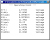
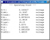
I added node names (labels) to all of the critical nodes in the circuit. I used LTSpice to compute all of the node voltages if the sender is replaced with a 20Ω resistor, and again if it is replaced with a 100Ω resistor. These correspond to empty and full. Look at the two tables of voltages.

With the table of voltages at all of the nodes in hand you should be able to tell what is not working. Note that I did not intend for you to use pots for R1, R2, R6 and R8. If you had used the 1% fixed resistors, the only one you might have to tweak is R6. If you just put pots everywhere, powered it up, I dont think you can set them to the correct values after the fact. If you preset them to within a % or two within the value on the schematic, you might stand a better chance.
 

Attachments

  • JeepFuelGauge.png
    JeepFuelGauge.png
    41.7 KB · Views: 459
  • JeepRS20.png
    JeepRS20.png
    9.8 KB · Views: 326
  • JeepRs100.png
    JeepRs100.png
    9.7 KB · Views: 327
Fuel Gauge / Sender compatibility

Hello people. I've been following this thread for an answer to my particular problem but it hasn't shown up, so here it is...
I'm building a dashboard for my bus using the SunPro 8219 fuel gauge. I intended to replace the existing sender with one made for the 8219 but then I found out it was near impossible to access the tank. So now I'm looking for some electronics to make the gauge read correctly. Here are the particulars-

Supply v => 12vdc
Sender => 0Ω empty, 88Ωfull
Gauge => 240Ω empty, 33Ω full
Note the inverse relationship.
Mathematically, the relationship works out to y = -2.95x+240
I was halfway thru building the op amp circuit that was in the 3rd or 4th post before I realized the inverse gain might be a problem.

How do I reconfigure the circuit to produce a negative gain?

Thanks in advance for your help
RagBus
 
Kind of like one of those adaptors that converts a stereo steering wheel controler from the cars oem to a different make, handy all being done ready for you.
 
Nope I dont think so, I looked into doing this myself one time.
Ended up playing around with can bus instead to get the job done.
 
Status
Not open for further replies.

Latest threads

New Articles From Microcontroller Tips

Back
Top