Continue to Site

Welcome to our site!

Electro Tech is an online community (with over 170,000 members) who enjoy talking about and building electronic circuits, projects and gadgets. To participate you need to register. Registration is free. Click here to register now.

  • Welcome to our site! Electro Tech is an online community (with over 170,000 members) who enjoy talking about and building electronic circuits, projects and gadgets. To participate you need to register. Registration is free. Click here to register now.

frequency counters

Status
Not open for further replies.

patroclus

New Member
Hello,

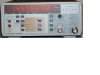
I would like to get a stand alone frequency counter, to measure unknown frequencies without requiring my usb logic analyzer and a PC.
I've seen quite cheap 1,3GHz units, and also 2,4GHz which is far more than I'd need. But there are things I don't plenty understand.

All unit have 2 inputs. 1Mohm and 50 ohm input impedance.
Only the 50 ohm input is able to measure frequencies above 25-50 MHz. This means that most of signals can't just be coupled. For example the output of an IC. As soon as the output resistance of the source circuit is above 500 ohm, the voltage divider makes the voltage measured in the unit drop around 10 times (+/-). Most of these counter have a sensitivity of 50 mVrms. This makes it unusable for output resistance around 5 komh at 5V levels.

How could this be worked around?
The first thing that comes to mind is use an emitter follower to lower impedance seen by the load (in this case the counter), but is a bit annoying to have to do this all times. Sure I'm missing something out. I never used these equipments before. The freq counter I use is inside my logic analyzer and works with standard TTL and CMOS levels.

Thank you for helping me getting to know one more thing in this fascinating world of electronics ;-)
 
My frequency counter (see attached piccy) has two inputs, Input A which is rated up to 160Mhz but will work to 250Mhz if you ask it nicely, and Input B which is rated to 2.6Ghz but will go to over 3Ghz.

Input A can be selected to have either a high impedance input (1Mohm) or 50 ohm.
Input B is fixed at 50 ohm.

One of the reasons for the 50 ohm impedance is that many of these counters are used in RF applications where 50 ohm is the standard for signal sources, loads and test equipment.

Using a high impedance at a high frequency is a bit of a non-starter because the stray capacitance, and the capacitance of any connecting cables will swamp the circuit under test and kill the signal you are trying to measure.
Your idea of using an emitter follower probe is a good one, but better still use and FET as a source follower, that way you can have a high impedance input and a long cable (with lots of capacitance) connecting to the counter.

Another thing to consider with "long" cables at high frequencies is standing waves.
If the cable as a quarter wavelength long at the frequency of interest, it is possible to have a short circuit at one end of the cable and the other end will appear as an open circuit.
Yet when the length is a half wavelength, a short circuit at one end shows as a short at the other end.
Weird stuff until you have seen it a couple of times.
Which brings is back to the 50 ohm inputs. If the system is properly matched to 50 ohms throughout, no problems.

JimB
 

Attachments

  • Racal 1999.JPG
    Racal 1999.JPG
    90.9 KB · Views: 233
Some oscilloscopes buffer one of the input channels onto an output on the back. That output will usually drive 50 :eek:hm: so you can just use a BNC cable from that onto the frequency counter.
 
But what happens if you use the frequency counter for digital circuits measurements? what output impedance is usual? imagine you want to know the clock period of certain digital system you're working on (supposing you did not design it, but want to find something out, repair, ..)
 
If a TTL output is around 12.5 kohm, if you try to measure the frequency into a 50 ohm counter input, you'd probably get no measure at all. If you feed the TTL output to an emitter follower, and then measure its output, this should be fixed, isn't it?
Bur I wonder why, if it is so easy, no freq counter has this option built in....
 
patroclus said:
If a TTL output is around 12.5 kohm, if you try to measure the frequency into a 50 ohm counter input, you'd probably get no measure at all. If you feed the TTL output to an emitter follower, and then measure its output, this should be fixed, isn't it?
Bur I wonder why, if it is so easy, no freq counter has this option built in....

You appear to be confused about what frequency counters are designed for?, usually it's for RF at high frequencies, everything in this range is 50 ohms, so it makes perfect sense for the frequency counter to also be 50 ohms.

The high impedance input normally exceeds the range of TTL anyway, so just use that for TTL.
 
yes, I might be confused. I'm not much into RF yet.
I just wanted to know if they could be used for digital circuits frequency measurements. Maybe it's just fine to use a digital oscilloscope for this

The high impedance input normally exceeds the range of TTL anyway, so just use that for TTL.

what do you mean? I don't see why a 1Mohm input should exceed a TTL output... maybe it me that I didn't understand you.
 
patroclus said:
If a TTL output is around 12.5 kohm, if you try to measure the frequency into a 50 ohm counter input, you'd probably get no measure at all. If you feed the TTL output to an emitter follower, and then measure its output, this should be fixed, isn't it?
Bur I wonder why, if it is so easy, no freq counter has this option built in....
The output of a TTL gate does not look like a 12.5k resistor. I realize you inferred this from the 400ua output sourcing current spec, but this is the worst case, and is specified with the output at 2.8V. I tested a 74LS04 on my bench, and at 25MHz, it drove about 3V p-p into 560 ohms, and over 1V p-p into 47 ohms. So, if you put a 510 ohm resistor in series with your output (put it on the end of the coax that goes to your TTL gate, not on the freq meter end), you will still have marginally valid logic levels on a typical gate.
 
patroclus said:
what do you mean? I don't see why a 1Mohm input should exceed a TTL output... maybe it me that I didn't understand you.

Not the impedance, the frequency, TTL is relatively low frequency, and the low frequency, high impedance, input on the counter should exceed what TTL runs at.
 
Oh yes, I know what you mean. But I said TTL, as an example. Imagine a FPGA based board, which may use 3.3v logic or whatever, and also an unknwon frequency.
 
patroclus said:
But what happens if you use the frequency counter for digital circuits measurements?
My first thought is "why would I want to do that"

patroclus said:
what output impedance is usual? imagine you want to know the clock period of certain digital system you're working on (supposing you did not design it, but want to find something out, repair, ..)
The first thing I would do would be to look using an oscilloscope, they are usually accurate enough. Unless of course the digital electronics requires some accurate clock for timing or some other measurement, only then would I use the counter.

JimB
 
Your frequency counter has a sensitivity of 50mV RMS, this doesn't mean it's the maximum voltage it will count, it just means that it will count the frequency of a signal providing it's >50mV RMS. Most frequency counters can accept input voltages of up to 250V peak, much higher than any TTL or CMOS gate.

If I recall correctly TTL gates have a fanout of 10, that means they can happilly drive impedances as low as 1k2.

Just stick a 1k to 2k2 resistor in series with the co-ax on the circuit side. With a peak voltage of 3.5V the input to your counter will be 78mV which is more than enough.

I don't see why this is a problem though, TTL doesn't work over 25MHz and your counter will have an input impedance of 1M at this frequency. The only time you need to bother about this is when you're playing around with ECL or some of the higher speed CMOS famillies.
 
Yes, I said TTL as an example, but it's high speed CMOS what really is making me consider this. For TTL I would use the high impedance input. But what about measuring frequencies in modern CMOS systems ?
 
When I say CMOS, I include microprocessors, memories, etc..
Many system have buses running at more than 100 MHz, for example.
 
Put 1950 (2k) ohms in series with your 50 ohm input. A 2V pk-pk signal will give you 50mV pk-pk at the counter. It will load your 3V cmos signal with 1.5 mA, which for most signals is nothing.
 
mneary said:
Put 1950 (2k) ohms in series with your 50 ohm input. A 2V pk-pk signal will give you 50mV pk-pk at the counter. It will load your 3V cmos signal with 1.5 mA, which for most signals is nothing.
In his first post, Patroclus says the sensitivity is 50mV rms. This means he needs a 100mV p-p square wave (AC coupled - DC doesn't count). I doubt the spec applies to any waveform other than 50% duty cycle.
If you are going to use a series resistor, it needs to be applied at the source, to minimize reflections in the coaxial cable.
 
Status
Not open for further replies.

Latest threads

New Articles From Microcontroller Tips

Back
Top