Continue to Site

Welcome to our site!

Electro Tech is an online community (with over 170,000 members) who enjoy talking about and building electronic circuits, projects and gadgets. To participate you need to register. Registration is free. Click here to register now.

  • Welcome to our site! Electro Tech is an online community (with over 170,000 members) who enjoy talking about and building electronic circuits, projects and gadgets. To participate you need to register. Registration is free. Click here to register now.

Frequency 150-700Hz to Voltage?

Status
Not open for further replies.
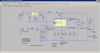
You will need the proper conditioning circuit to feed the rev signal to the lm2917.
You should cuple it using a cap a maybe a zener to keep the input voltage below max for the chip.
You may or may not need the diode on the ground pin.
I looked quick and did not see any circuits that would work with the ignition circuit on your bike.
 
Hi AG..

He is making a "shift light" that lights at a certain engine RPM when the gears should be shifted to avoid over-revving the engine.
The datasheet for the LM2907/LM2917 shows a "normal" engine application but the inputs are a magnetic variable reluctance pickup or breaker ignition points for car engines.

So...does the OP want one LED that lights at, or above, a certain RPM?
Or multiple LEDs that light at different RPMS?
Or user selectable RPM value?

thx

eT
 
Last edited:
Hi AG..


So...does the OP want one LED that lights at, or above, a certain RPM?
Or multiple LEDs that light at different RPMS?
Or user selectable RPM value?

thx

eT
I think one LED that lights at, or above, a certain RPM.
 
Thank you guys for interesting!! My test bike, have a 1 cyl, and 2 stroke engine. I want to LED lights at the desired speeds (rpm), usually between 6000-8000rpm.
 
Which RPM do you want it to light?

On 7000rpm.


I have a speedo sensor with 3 wires on my bike (positive, negative, and signal). Today I measured between signal and negative wire a output frequency:
10km/h = 20Hz
15km/h = 30Hz
20km/h = 40Hz
50km/h = 100Hz

I dont know which type is sensor (can you identify with this parameters?), but when signal going out, a voltage is 4.25V, then drop on 0V (resistance is 43.8ohm), and again going to 4.25V, like a pulses or logical 0 and 1 ?


Can i connect some f/v converter to speed sensor?
 
Last edited:
Hi...


I'm thinking we can pick the signal off the ignition pickup sensor (low voltage ac) but the numbers you've
listed are not what I expected. I thought the sensor would reflect 1 RPM = 0.0166667 Hz. So 2000 RPM=33.3333 Hz but its not matching the values you've listed..?

eT
 
Is your "speedo sensor" before or after the transmission (gear box)?
 
Hi...


I'm thinking we can pick the signal off the ignition pickup sensor (low voltage ac) but the numbers you've
listed are not what I expected. I thought the sensor would reflect 1 RPM = 0.0166667 Hz. So 2000 RPM=33.3333 Hz but its not matching the values you've listed..?

eT

Im connected a multimeter on negative, and positive wire from pickup, and then turn on Hz metering.

Is your "speedo sensor" before or after the transmission (gear box)?


Sensor position is directly on front wheel.
 
Well maybe with the right signal conditioning circuit.
Be your problem is with the signal conditioning circuit anyway so why bother.
 
Hi :)

Ok here's something you can try...but I'm not certain about the measurements you've shown.
The frequencies seem high and aren't very linear.:confused:
But anyway...if you can pick the signal off the "Red" wire (0-3VAC), this might work.:meh:

eT
 

Attachments

  • F2VCkt6.png
    F2VCkt6.png
    32.8 KB · Views: 201
  • F2VSim6.png
    F2VSim6.png
    18.7 KB · Views: 184
Status
Not open for further replies.

New Articles From Microcontroller Tips

Back
Top