Continue to Site

Welcome to our site!

Electro Tech is an online community (with over 170,000 members) who enjoy talking about and building electronic circuits, projects and gadgets. To participate you need to register. Registration is free. Click here to register now.

  • Welcome to our site! Electro Tech is an online community (with over 170,000 members) who enjoy talking about and building electronic circuits, projects and gadgets. To participate you need to register. Registration is free. Click here to register now.

Frequency 150-700Hz to Voltage?

Status
Not open for further replies.

joza18

New Member
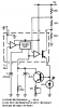
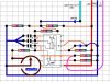
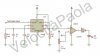
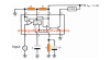
Hello, I have a source (wire from cdi to coil) with 100-250VAC with frequency from 150 - 700Hz depending a rpm on my bike. Im trying to do something like a shift light with one turned LED on some rpms.

I tryed with LM2917 and several options, but it doesn work :confused:

Do you have a any suggestion please?

Thank you!
 
Have you checked the biker forums?
I have seen many designs in them.
 
How are you picking up your rev signal?
From the coil or crank sensor?
 
The circuit you posted with the LM2907 tach IC does not work because the input (pin 1) of the LM2907 needs a DC path to ground, usually provided by a magnetic pickup.
Try the circuit after adding a 100k resistor from pin 1 to ground.
 
Hi

I can generate a simulation.
What is the desired frequency range and full scale voltage output?
Also, the number of engine cylinders and max RPM?
Also, what is the LED suppose to indicate?

eT
 
Thank you guys for interesting!! My test bike, have a 1 cyl, and 2 stroke engine. I want to LED lights at the desired speeds (rpm), usually between 6000-8000rpm.

I tryed to do about 10 versions. Here is a photo: http://www.dropbox.com/s/qf6q6yazhoczugb/20140529_093310.jpg

OK, now i will show you a service manual for bike, I tryed to take a signal from green wire primary (i tryed from pickup too): http://www.dropbox.com/s/cdtp9i3wpnantf6/Screenshot 2014-05-28 11.29.00.png

Here are other parts in ignition: http://www.dropbox.com/s/k20leosf38nb61w/Screenshot 2014-05-28 11.29.23.png


Here is a frequency result from green wire to ground, voltage is from ~150V - 200VAC
2000rpm - 150Hz
3000rpm - 250Hz
4000rpm - 330Hz
5000rpm - 450Hz
6000rpm - 500Hz
7000rpm - 600Hz
8000rpm - 700Hz
9000rpm - 1300Hz

And here is from pickup red wire to ground:
2000rpm - 380Hz
3000rpm - 530Hz
4000rpm - 750Hz
5000rpm - 950Hz
6000rpm - 1000Hz
7000rpm - 1200Hz
8000rpm - 1400Hz
9000rpm - 1530Hz

Voltage on 1800rpm is 0.7VAC, on 5000rpm is 1.5VAC, on 7000rpm is 1.9VAC, on 9200rpm is 2.3VAC.


And These are schemes by which I worked:

**broken link removed**

**broken link removed**

http://www.next.gr/automotive/automotive-circuits/overspeed-indicator-l12548.html

**broken link removed**

http://www.piergm.com/elettronica/shiftlight.htm


Now Im trying to do it this:
**broken link removed**

or this:
http://i134.photobucket.com/albums/q90/versamson/Tacho Project/pcb_lm2917.jpg
 
Last edited:
Please attach your schematics to your posts HERE instead of over at UPLOADS where we cannot open or at PHOTOBUCK that takes a long time to open.
Did you try adding a resistor to ground on the pin 1 input of an 8-pins tach IC so that it has a 0V DC reference voltage? The other input is pin 8 which is connected to ground so its DC reference voltage is 0V.
 
Sorry, I didnt know that. Here is uploads...

Please attach your schematics to your posts HERE instead of over at UPLOADS where we cannot open or at PHOTOBUCK that takes a long time to open.
Did you try adding a resistor to ground on the pin 1 input of an 8-pins tach IC so that it has a 0V DC reference voltage? The other input is pin 8 which is connected to ground so its DC reference voltage is 0V.

I tryed with this, 2x 10k from input to ground.
shift_light2_600.jpg

Voltage on exit from lm2917 is same like on power supply (+12V), no changes. I know that voltage on exit must be variable, depending a freq on input.
 

Attachments

  • 135-9038.png
    135-9038.png
    9.7 KB · Views: 754
  • frequency-to-voltage-converter-circuit.png
    frequency-to-voltage-converter-circuit.png
    22.1 KB · Views: 1,341
  • pcb_lm2917.jpg
    pcb_lm2917.jpg
    84.5 KB · Views: 2,517
  • Screenshot 2014-05-28 11.29.00.png
    Screenshot 2014-05-28 11.29.00.png
    65.3 KB · Views: 403
  • Screenshot 2014-05-28 11.29.23.png
    Screenshot 2014-05-28 11.29.23.png
    89.4 KB · Views: 457
  • SHIFT_LIGHT1.jpg
    SHIFT_LIGHT1.jpg
    26.9 KB · Views: 1,490
  • simple speed limit switch circuit.png
    simple speed limit switch circuit.png
    25.4 KB · Views: 774
  • spia_fuorigiri_schema.gif
    spia_fuorigiri_schema.gif
    15 KB · Views: 867
Please attach your schematics to your posts HERE instead of over at UPLOADS where we cannot open or at PHOTOBUCK that takes a long time to open.
Did you try adding a resistor to ground on the pin 1 input of an 8-pins tach IC so that it has a 0V DC reference voltage? The other input is pin 8 which is connected to ground so its DC reference voltage is 0V.


Yes I tryed and nothing happen.


Today I worked with this schematic (IC is lm2917, 14pin version, a second diode (zener) is 1N4148):
pcb_lm2917-jpg.86514


Nothing happen again, 0V on out is always, but between input (ignition coil wire) and ground is 1.6V.
A source is motorbike, diesel car (alternator W signal), and transformer from 230VAC to 2.8VAC, 50Hz.
 
Since you used an LM2917 IC in an 8-pins case, its 7.5V zener diode was blown up since you connected it to a 12V supply. The heat might have destroyed the IC.

The circuit layout posted in post #10 shows an arrow instead of a 1N4148 diode at its input. It also shows an arrow instead of a diode at pin 11. These diodes might be backwards.
Please post the schematic instead of the circuit layout.
 
I dont have a schematic from post #10, only this pic :( The guy made a tachometer with 20 leds on other forum, on Vout he merged to input a LM3914-->Leds.
My problem is 0V on output from lm2917.
 
I do not know what are the voltage levels of the pulses from your ignition coil.
I do not know which end of the 1N4148 is the cathode since it is not the symbol for a diode. It seems to be backwards.
I do not know if the other diode is a zener diode and I do not know its voltage rating. Again I do not know which end is which.
 
I do not know what are the voltage levels of the pulses from your ignition coil.
From 150 to 200VAC.

I do not know which end of the 1N4148 is the cathode since it is not the symbol for a diode. It seems to be backwards.
I connect like thispcb_lm2917.jpg

I do not know if the other diode is a zener diode and I do not know its voltage rating. Again I do not know which end is which.
Both diode are 1N4148zenerica.jpg
 
Last edited:
Both diode are zener diode, and both are 1N4148.
A 1N4148 is not a zener diode.
 
From 150 to 200VAC.
Then you have destroyed the LM2917 because its datasheet says its maximum allowed input voltage is only +28V.
The diode at the top is connected backwards so it passes the high voltage to damage the input of the IC but it blocks a logic low so the IC will not work even if the voltage is reduced and the IC is replaced.
 
A 1N4148 is not a zener diode.
Sorry my bad, Im tired because Im trying to do it this about 3 weeks.


Then you have destroyed the LM2917 because its datasheet says its maximum allowed input voltage is only +28V.
The diode at the top is connected backwards so it passes the high voltage to damage the input of the IC but it blocks a logic low so the IC will not work even if the voltage is reduced and the IC is replaced.

Damn! I will buy a new one.


I have sa speedo sensor (digital speedometer) on my bike with hall effect (without intensity 1=0) 3 wire:
Positive +12VDC,
Negative -ground,
Signal wire.

Should I connect a lm2917 to that sensor? And wich one schematic is good for that sensor?
Thanks!
 
Last edited:
The signal from your speedo hall effect sensor probably does not go below ground so the 8-pins versions of the LM2907 or LM2917 cannot be used.
One of your schematics has the reference input biased at +0.7V with a diode but the signal input is biased at +8.1V which is odd.

I think the reference input should be biased at half the supply voltage so then the sensor input can swing above and below it easily.
 
Hi

Here's something I threw together.
I'm still not sure what the OP wants for LED indication. Just light up between a certain voltage range?
Output is ~500mv per 1000 RPM

One image at 10000 RPM
One image stepped 1000 thru 10000 RPM

eT:)
 

Attachments

  • F2VCkt1.png
    F2VCkt1.png
    134.3 KB · Views: 401
  • F2VCkt2.png
    F2VCkt2.png
    173.2 KB · Views: 374
Last edited:
He is making a "shift light" that lights at a certain engine RPM when the gears should be shifted to avoid over-revving the engine.
The datasheet for the LM2907/LM2917 shows a "normal" engine application but the inputs are a magnetic variable reluctance pickup or breaker ignition points for car engines.
 
Status
Not open for further replies.

Latest threads

Back
Top