Continue to Site

Welcome to our site!

Electro Tech is an online community (with over 170,000 members) who enjoy talking about and building electronic circuits, projects and gadgets. To participate you need to register. Registration is free. Click here to register now.

  • Welcome to our site! Electro Tech is an online community (with over 170,000 members) who enjoy talking about and building electronic circuits, projects and gadgets. To participate you need to register. Registration is free. Click here to register now.

flashing lights

Status
Not open for further replies.

veste75

New Member

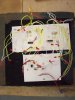
Hi all I happen to be a trainee teacher and I am totally new to electronics, over the past few months I worked on a small electronic project, which was all about connecting an IC 555 astable mode, with a double 4017. All I wanted to achieve was simply a motion light for a D/T secondary school toy project. The circuit was drawn using PCB wizard, which did a great job, but unfortunatley I would not know now how to explain this diagramm to a 12 year old, neither to my teachers, plus it doesn't even work.see attachments
I would not mind also just if any of you out there colud tell me in simple terms how this two circuits can be connected triggering the LEDS to light up in numerical order.

Best whishes

veste
 

Attachments

  • 100_1734.jpg
    100_1734.jpg
    607.1 KB · Views: 179
  • scan0004.pdf
    539.6 KB · Views: 175
  • scan0003.pdf
    4.3 MB · Views: 215
hi,
The first obvious point is that pins 15 [MReset] of the 4017's are floating when the RESET p/b is not pressed.
This could cause mis-operation.

What symptoms does the project show.??
 

Attachments

  • AAAimage01.gif
    AAAimage01.gif
    368.9 KB · Views: 848
Last edited:
You should look at the datasheet of the CD4017 to see the power supply pins.
Pin8 is 0V and pin16 is +ve.

The R pin15 of each CD4017 should have a 10k resistor to 0V.

The battery should have a 100uF bypass capacitor in parallel with it.

I didn't check the pcb nor the maze of wires all over the place.
 
Last edited:
try this circuit.....you need to use yr 555 circuit to drive the attatched circuit in the uploaded file.....it has all the necessary gating and the switch on reset circuit included to clock two 4017s one after the other.....pin 15 0f the 4017 is the reset pin for the counter which when taken hi the counter is reset,the gating is arranged so when the first counter reaches its end of count it is inhibited and the second counter is enabled until that reaches its end of count and then its final count output then resets both ics and the whole sequence starts again with the first counter active then the second counter,then reset to start again....
 

Attachments

  • 2stage 4017 counter.pdf
    8 KB · Views: 144
Last edited:
hi veste,
If there has been the possibility that the voltage rails have been crossed over the 4017's will most likely be 'dead'.

The 4017 power pins are pin16 is +V and pin8 is 0V, check the pcb copper track to ensure that is how they are wired.

Add the two 10k's on the MR pins of the 4017 also a 470uF cap across the +V and 0V rails,,, as shown in the edited dwg.

what dwg stands for?and where can I find it?
 
I think you should neaten up your practical work before you start teaching electronics. Make the board smaller, mount the resistors neatly and flat on the board and get rid of those flying leads and solder the LEDs directly to the board.

You might think I'm being picky but many errors can result from sloppy construction rather than bad circuit design. When you get to do more skilled projects which involve high frequencies low currents or high impedances neat and compact construction becomes mandatory.
 
Hi veste,

how about that circuit design?

It drives 24 LEDs from three cascaded decimal counters (HCF4017) and includes driver transistor arrays for highest possible LED brightness.

The board size is determined by the number and diameter of the LEDs. (Used: 24LEDs at 5mm diameter)

Board size: 6.3X1.9"

Clock frequency can be varied from 27 to 110Hz.

I agree with hero999 considering circuit construction. There are too many wires with the possiblity of faulty connections, resulting probably in fried IC's instead of a functioning circuit.

The attached circuit has not been tested yet, but the simulation is right.

Boncuk

P.S. If you want to see a real "Veste" google for Veste Coburg, a strong fortress (wall thickness 1.5m) which defeated Wallenstein's siege in the middle ages. Prince Albert (Earl of Sachsen-Coburg-Gotha) should also be well known in the UK (at least in the Royal family).
 

Attachments

  • LAUFLICHT-SCH.pdf
    85.6 KB · Views: 160
  • LAUFLICHT-BRD.pdf
    72.6 KB · Views: 145
Last edited:
Status
Not open for further replies.

Latest threads

New Articles From Microcontroller Tips

Back
Top