Continue to Site

Welcome to our site!

Electro Tech is an online community (with over 170,000 members) who enjoy talking about and building electronic circuits, projects and gadgets. To participate you need to register. Registration is free. Click here to register now.

  • Welcome to our site! Electro Tech is an online community (with over 170,000 members) who enjoy talking about and building electronic circuits, projects and gadgets. To participate you need to register. Registration is free. Click here to register now.

Fixing an Aune T1 (amp/dac) TUBE DAC Board

Status
Not open for further replies.
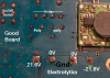
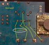
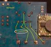
There appears to be a track fault on the board, under the capacitor or other component - possible a poor plated through hole or possibly a failure due to vibration / thermal expansion over time.

The simple cure is add a wire link to the points at the ends of your red line, to bypass the fault.

Use a reasonably thick wire and be careful not to short to the bulk copper areas around the pads.
Or, if you have some Kapton tape, put a couple of layers of that between the two pads so the edges are overlapping the clearance areas, then use a solid jumper soldered over the two.

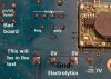
Edit - it's around that black wire-ended part, if I'm not mistaken. Is that an inductor that could have failed? It's very difficult to make out the PCB tracks..
 
Last edited:
cowboybob

Readings are mostly the same. I put a picture with the good board as for the bad board, on the plus side, before I turned it on it was at + a few hundred mV. When I turned it on the Voltage started dropping, constantly but very slowly so I discharged the cap and turned the board on again at it went into the negative Voltage and kept dropping very slowly. I assume it would get to -100mV in few a minutes and keep going down. When I turn the board off the voltage starts rising, again very slowly and I assume it will get to + a few hundred mV again over night, though I will have to see later.

Also like I said before C33, the poly cap before L3 and the +side electrolytic cap, discharges very slowly after turn off on the bad board, unlike C34 and both C33 and C34 on the good board.


rjenkinsgb

Regarding the wire, is there a chance the trace originally does not connect directly like I have drawn the continuity lines, would that even matter and could that affect anything in the short or long term?


If you mean the thing in the third picture, it’s marked L3 so I assume it’s an inductor. Again I have no idea why it’s there, what it’s doing, what happens if it brakes, etc.
 

Attachments

  • goad board.png
    goad board.png
    384 KB · Views: 195
  • bad board.jpg
    bad board.jpg
    92.9 KB · Views: 193
  • L3.jpg
    L3.jpg
    742.9 KB · Views: 197
Does that L3 have continuity through it, measured directly on its leads?
If that is open circuit, you have found the fault.

If not, it's likely a PCB track fault as before.
 
bg,

(rjenkinsgb beat me by 4 minutes :banghead:)


In a power supply, an inductor is often placed between two electrolytic caps as part of the 60 (or 50) Hz filtering circuit.:
1540332563130.png


The one in your photo:
1540332063946.png

looks a tad "rough", as in overheated at some point.

Test it for continuity.
 
Sorry I didn't write what it is on the continuity picture I've uploaded before, problem is it has continuity on both boards. I've tested it again measuring directly on the leads and they both have a ~0.3ohm resistance which is more or less the same thing I get when I touch the leads together so maybe the manufacturer is just screwing with people.

The end of L3 that is not connected to anything in the pictures has continuity with C38 on the other side on both board.

Is it still most likely the lead? Also I've asked before "Regarding the wire, is there a chance the trace originally does not connect directly like I have drawn the continuity lines on the good board, would that even matter and could that affect anything in the short or long term?". I understand this may not have a simple answer I just want to know if it's possible or what to look for.

PS: Is it not very odd to have no components broken and a blown trace?
PPS: The "rough" look is mostly from the camera, it only looks marginally worse than the one the good board.
 

Attachments

  • Good Board.jpg
    Good Board.jpg
    341.1 KB · Views: 185
  • Bad Board.jpg
    Bad Board.jpg
    340.1 KB · Views: 188
Last edited:
In that case it is a PCB track that's failed.

Can you tell from the good one which end of the inductor the bridge rec pin connects to, by the resistance?
If you can, link it to that on the faulty board, otherwise just connect it straight to the pin on the main smoothing cap.

It looks like there is a little switched mode PSU of some sort to the right of the photo, the inductor could be part of the filtering to avoid interference from that - in which case it's not in the connection between the bridge and cap, it's a take-off point from those.

Edit - reading again, it's unlikely to be "blown" due to overload - PCB joints/tracks can crack due to vibration (especially under heavy components) , or if the through-hole plating was not very good and the solder did not fully flow through to the top side track on the board, under one of the large components, the plated connection could fail due to repeated switch-on surges etc..
 
Last edited:
bg, it might be worth the effort to first just "re-flow" the solder points within the ovals in the pic below:
1540393234900.png

on the off chance that the continuity break is at/in one of the vias.

If that proves to not be the case, you could then remove the two large electrolytics (fairly simple and easy) and look for a damaged/blown trace under one of them.
 
I think my leads have too much resistance to tell where it connects but I will try again, after that I'll try reflowing and if that does not work I'll remove the cap to check the traces.
 
One step forward two, probably more than two, steps back


Half of the positive pad of the big cap was burned but I reflowed it and I got continuity (red line in the previous post where I wasn’t getting continuity). I turn the board on and after a short while I got smoke from the general area I was working on, on the side with the components, so I turned it off.

Turns out I should not have hurried up to plug it in, while there is continuity there is also a resistance of at least 2ohms, sometimes it’s 3 or more, the readings vary.

I got out my cheap ESR meter again and got the following readings:

The small poly cap on the +side (c33) was reading as 3612uF (obviously not right but that’s what it was in circuit) whilst on the bad board it was 7609uF. After the smoke it’s reading as resistor with the similar resistance to the leads (0.12ohm).

The small cap with connections on the other side (c38) is a similar story, 3566uF on the good board, 8003uF on the bad board before the smoke and now it’s reading as a 0.27ohm resistor.


1.Am I correct in assuming these two are both gone?
2.Could the resistance to the electrolytic cap be the cause of these two going up in smoke or is it likely something else was bad and caused this?
3. Anything to note before I pull all 3 of the board to see what’s what and if anything else is gone?

PS: the KIS-3R33S Vin has continuity with the ground, it was fine before. I have had to resolder the Vin after some previous tests and as bad as my soldering may be I doubts that's the reason, I think this happened when I powered it on, along with the smoke. Just to make sure does this indicate the KIS-3R33S is gone as well or can it be something else? Also is it possible this has any programing or are they all the same and it can just be replaced with one I may pull of something else?
 
Last edited:
First, very carefully visually check those circular and square soldering pads you have re-flowed for possible shorts to their surrounding "plane" (I am assuming that "plane" is a ground "plane").

Testing caps in-situ is iffy, at best. uF values for the poly (orange) caps is highly unlikely.

I'd suggest pulling both poly caps, both electrolytics and the inductor. Then check them.

This will also allow you to check ALL the associated traces.
 
I know the value makes no sense, I was just comparing the value with the working board to maybe tell what's wrong but I thought it broke because I get a resistance of less than 0.2ohms when I measure it, I will pull it out though for further testing.
Also I just updated my last post, regarding the KIS-3R33S, can you give me any input on that?

I think I've mentioned this before when I started the thread but I think I should mention it again so that you any anyone else won't think I'll blame them for braking my board or anything along those lines. I am trying to fix it but I am doing this for fun and to learn, even if I brake this thing worse than I just did I'll probably learn something so I don't mind at all and thanks for the many and timely replies!
 
I'm in two minds here if the OP is a scammer or what?, we're up to 72 posts over a circuit with almost zero components in it - such a circuit (if it could even be called that?) would only take seconds to fault find and repair.

From what I can gather, there's voltage at one part of the circuit, but nothing coming out - it can ONLY be a break in that VERY tiny part of the circuit.

There's certain people on the Internet who (for what ever reason) try to keep pointless threads going for as long as possible, I'm starting to think he's one of those?.
 
Like I said I know very little about this , I assumed a very small part of it was broken, I didn't know what and I assumed someone can help me get it over fairly faster and that it would be a more interesting way of learning. Now that there was smoke coming of the board I think the problem is considerably more complicated (though it may very well still be simple for someone with experience). I'll try to learn more of the basics and come back when I have something meaningful.
 
Thanks, Nigel. It was getting a bit frustrating at this end... :banghead:.
... I'll try to learn more of the basics and come back when I have something meaningful.
bg, thanks for recognizing your best next move... :cool:.
 
Status
Not open for further replies.

Latest threads

New Articles From Microcontroller Tips

Back
Top