Continue to Site

Welcome to our site!

Electro Tech is an online community (with over 170,000 members) who enjoy talking about and building electronic circuits, projects and gadgets. To participate you need to register. Registration is free. Click here to register now.

  • Welcome to our site! Electro Tech is an online community (with over 170,000 members) who enjoy talking about and building electronic circuits, projects and gadgets. To participate you need to register. Registration is free. Click here to register now.

Ferrite Bead

Status
Not open for further replies.

kinarfi

Well-Known Member
I was advised use a ferrite bead and a 10Ω resistor on the gate of a power Mosfet and the project I'm working on needed 2 of them and I only had one and an idea came to me, what would happen if you drilled a hole in a piece of aluminum and used it instead of a ferrite bead? It would still create some inductance, wouldn't it? but how much? I tried to measure the inductance of a piece of wire with a ferrite bead on it and it couldn't be measured, not with my equipment, or what would happen if you used a small washer? A ferrite bead is made of powdered magnetic material and is not conductive, where as aluminum or a washer is. I kept looking until I found a 2nd ferrite bead, but I still wonder what would happen with the aluminum or the washer, any one know?
Thanks
Jeff
 
The whole point in using a ferrite bead is that it is ferromagnetic. It has a high permeability which increases the inductance of the wire passing through it. Aluminum is not ferromagnetic, and has a permeability roughly equal to that of air.
 
Probably iron bead is little better than aluminum at least. Once I also was searching ferrite beads and getting nothing. When I went to a garbage store, there were tens of beads and tens of VERY rare and exciting parts used in damaged and old kits. I scrapped them free because they do not know what they have on their recycle bin. :)
 
According to your "advisor", what is adding a ferrite bead to the gate of a FET supposed to do?
 
Adding a bead (to stop ringing on the gate) but it might cause more ringing.
The gate has capacitance. Adding inductance does not sound good. You need a bead that looses power. AND A resistor to reduce the ringing.
 
According to your "advisor", what is adding a ferrite bead to the gate of a FET supposed to do?
I would have to search to find who my "advisor" was, but I seem to have fewer FETs destroyed and I have seen it on other FETs I have salvaged, mostly from power supplies for servers.
 
My interest has been piqued by this thread, so I thought that I would run a few tests to see the effect of various beads and a steel nut.

Using a spectrum analyser and tracking generator and a little test jig which is shown with the beads and nut in the first picture:
Test Jig and Beads.jpg

With the analyser sweeping from zero to 100MHz, the response of the straight through connection is shown here:
Straight through connection.jpg
The vertical scale is 2dB per division. The big dip at the left of the screen is the zero frequency marker.

Putting the steel nut on the wire shows practically no change from the straight through connection:
Steel Nut.jpg

The small bead gave some attenuation as shown here:
Small Bead.jpg

The larger bead gave a bit more attenuation, as shown here:
Bigger Bead.jpg

Remember that this is taking place in a 50 ohm environment, where the circuit impedance is something else other than 50 ohm the attenuation will be different.

Going back to the original question, a steel nut does nothing, and aluminium washer is likely to do even less.

JimB
 
A capacitive discharge with desired C ratio Csource/Ciss and driver ESR to limit current will shut off a MOSFET faster
Then slow turn on gives good dead band for bridge control. But most just use R//Diode with voltage driver to control non-linear ramp.
Remember Gate charge steps rapidly during switching time which results in dynamic current spike then low current in either Vgs state. In this case Ic=V*dC/dt dominates over C*dV/dt.

where Q=CV and when both are a function of time Q(t)=C(t)*V(t) and Q(t) has a step function near threshold voltage. See Q vs Vgs.

https://www.onsemi.com/pub_link/Collateral/AND9083-D.PDF
 
Last edited:
My interest has been piqued by this thread, so I thought that I would run a few tests to see the effect of various beads and a steel nut.

Using a spectrum analyser and tracking generator and a little test jig which is shown with the beads and nut in the first picture:
View attachment 91166

With the analyser sweeping from zero to 100MHz, the response of the straight through connection is shown here:
View attachment 91167
The vertical scale is 2dB per division. The big dip at the left of the screen is the zero frequency marker.

Putting the steel nut on the wire shows practically no change from the straight through connection:
View attachment 91170

The small bead gave some attenuation as shown here:
View attachment 91169

The larger bead gave a bit more attenuation, as shown here:
View attachment 91168

Remember that this is taking place in a 50 ohm environment, where the circuit impedance is something else other than 50 ohm the attenuation will be different.

Going back to the original question, a steel nut does nothing, and aluminium washer is likely to do even less.

JimB


Hi there,

There is a chance that the permeability of the ferrite is about 10 times that of the steel, so if you want to do one more test try it with ten steel nuts on the same wire, or wind 10 turns through the center of the nut as if it were a toroid, and see if you can get a reading that is closer to the single ferrite bead.

The permeability of the steel is probably about 100, while that of the ferrite could be 1000.
 
A capacitive discharge with desired C ratio Csource/Ciss and driver ESR to limit current will shut off a MOSFET faster...

I understand gate charge control which all happens in the 0 to a couple of MHz range, but I was wondering what a bead that can only produce effects at >50MHz has to do with it?
 
gate charge effects are not 0~ couple MHz rather,
0 to 1 μs.
and 20ns for a good Mitsubishi 150A IGBT

Which is ~ 30 MHz

But too fast and you get EMI problems.

In my experience with RF and logic noise a ferrite bead is like adding 5 pF across a 50 ohm driver. The lossy part comes from the driver but in the bead it is absorbed in the ferrite.
 
Last edited:
1/1us = 1MHz!

Ferrite beads are useful when the rise time is measured in 10's of ns.
 
1/20 ns = 50MHz

There are two categories of ferrite beads with hundreds of sub cat.

1) high mu ( low metallic oxide content, high resistance with probe, good for video signals on VGA cable , SMPS cables, DC cables, CM chokes for data, HDD read/write cable to heads etc.


2) low mu ( high metallic oxide content, low resistance with probe/ohmmeter, good for UHF, microwave )
 
Tony, you missed the point. Nothing around the gate of a FET is happening at much over 1Mhz.
 
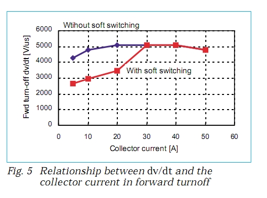
Not in my experience. A lot happens up to 30MHz in high performace MOSFETs and IGBTs with about 5kV/us

In fact Mitsubishi IGBT's are so fast they have to introduce soft switching technology to reduce EMI issues > 100MHz
 
Watching with great interest,Untitled.png the bead's effect on the circuit would only be at the rise and fall of the square wave, output of a LM555, so wouldn't that be the equivalent of a frequency greater than 10MHz since wave form is linear and not sinusoidal?
 
The DIP switch PS51259-A has a Trr of 0.13µs (typ) with inductive load.

sixth- generation pseudo-0.35µm trench MOSFETs which have lower RdsOn could be faster without mitigation.
 
If slew rate control of load is desired ferrite or additional gate capacitance may help, but degrade deadtime control in bridge designs and worse increase SOA dynamic power losses in high f PWM switches.

Thus slew rate control with filters is a tradeoff between switching loss and EMI so ferrite or additional C on gate is not wise for high speed PWM
 
Of course there may be up to 20 harmonics in slew rate and Mitsubishi geometry in MOSFETs and IGBT's tries to suppress the harmonics with nonlinear filtering effects in their IGBT modules.
Typ. MOSFETs may not have same response.

3949531300_1425669351.jpg


5450889200_1425669350.jpg

1200619500_1425669351.jpg


When it comes to MOSFET design, I consider Mistubishi the experts, which is why they can design modules with ganged IGBT's to switch a gigawatt of power. So for low power applications like this OP"s , I recommend learning from them.
 
ESL on both the gate and the load is bad practice for high speed switches. Generally they choose Litz wire and low ESL cabling to reduce transient effects from inductance getting referred back to gate capacitance with resonance and SOA issues. the advantage of IGBT's over MOSFETS is the bipolar output reduces Qg.
 
Status
Not open for further replies.

Latest threads

New Articles From Microcontroller Tips

Back
Top