How do I know if a toroid will work for 100 KHz and 1500 watts. I need to wind it with #12 solid copper wire.
Toroid Core FT140-43 Ferrite | eBay
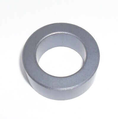
One FT140-43 Toroid Core. Ht = 0.500 in / 12.7 mm +/- 0.50 mm. ID = 0.900 in / 23.0 mm +/- 0.55 mm. OD= 1.400 in / 35.55 mm +/- 0.75 mm.
www.ebay.com
