Electro Tech is an online community (with over 170,000 members) who enjoy talking about and building electronic circuits, projects and gadgets. To participate you need to register. Registration is free. Click here to register now.
Welcome to our site! Electro Tech is an online community (with over 170,000 members) who enjoy talking about and building electronic circuits, projects and gadgets. To participate you need to register. Registration is free. Click here to register now.
HI
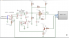
i use this circuit in LC meter
L1C1 are the tank circuit but where is the feedback for this L1c1 to make oscillator
its output is a sin wave but i don't know where its feed back
The comparator, together with R1/2/3/4/5 and C4, form a schmitt-trigger oscillator. Without C3 connected, it will oscillate at some low frequency (in the vicinity of 0.6/R2/C4 Hz). The voltage on C4 will oscillate between 1/3*Vcc and 2/3*Vcc, the comparator output will be either 0V or Vcc (roughly), and the comparator +ve input will be either 1/3*Vcc or 2/3*Vcc.
When you connect C3 and the LC resonant circuit, things change. When the comparator changes state, some charge will flow through C3 and will excite the LC tank. The LC tank will resonate and will trigger the comparator, which will in turn provide another charge through C3 (every half cycle) to keep the LC circuit oscillating. The frequency output by the oscillator is now determined (mostly) by the L and C values.
It's true that C3 blocks DC but it pass through AC. It's role is loss less AC coupling of LC tank to LM311 oscillator.
Reactance (AC resistance) of C3 at 1kHz is only 15.9 ohms which can be neglected.
This site uses cookies to help personalise content, tailor your experience and to keep you logged in if you register.
By continuing to use this site, you are consenting to our use of cookies.

 ).
).