4electros
New Member
panic mode said:it's true... well i still haven't seen confirmation that circuit is powered correctly. are you using dual voltage and not just one and same 9V battery? did you measure 9V between positive rail and ground? how about negative 9V rail and ground?
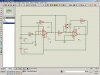
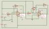
I powered the circuit in this way:
")