Continue to Site

Welcome to our site!

Electro Tech is an online community (with over 170,000 members) who enjoy talking about and building electronic circuits, projects and gadgets. To participate you need to register. Registration is free. Click here to register now.

  • Welcome to our site! Electro Tech is an online community (with over 170,000 members) who enjoy talking about and building electronic circuits, projects and gadgets. To participate you need to register. Registration is free. Click here to register now.

Excessive Current damaging the components of the circuit.

Status
Not open for further replies.

mpapreja

New Member
Dear Experts

This is the first time i am posting thread in this Forum. I am a beginner w.r.t. electronics. I am using one circuit comprising of
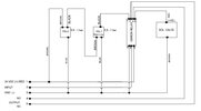
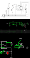
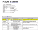
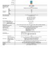
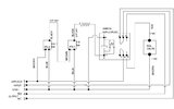
1. Pressure Switches 2 Nos. connected in series (specifications attached)
2. Omron Relay 1 No. (G2R-2-SND DC24) 3. Solenoid Coil (24 V DC) 1 No.
The circuit is working fine. We supply components with this circuit within a panel. We have supplied numerous panel but in some of the panels we are facing a problem of failure of 1st Pressure Switch. As per our observation this problem occurs due to excessive current flown in circuit.
Can somebody help to resolve the above issue. Your assistance in this regard would be highly appreciated.
 

Attachments

  • 1-Original Circuit.jpg
    1-Original Circuit.jpg
    50.4 KB · Views: 180
  • 2-Pressure switch specs.jpg
    2-Pressure switch specs.jpg
    247.7 KB · Views: 188
It appears that the first pressure switch powers the second pressure switch, which in turn power the relay.

The G2R-2-SND relay contains a diode to reduce the inductive voltage spike when the relay is turned off. The diode is fitted so that pin 8 is the positive connection, and pin 1 is the negative (https://assets.omron.eu/downloads/d...-s_(s)_general-purpose_relay_datasheet_en.pdf on page 9)
Your circuit shows the relay coil being the wrong way round. The diode will short out the output of the pressure switches. I don't know why the circuit is working at all, but there could be something in the relay that limits the current in the diode.
You should check the polarity of the relay coil. Pin 8 should be at 24 V when the relay is on. Also you should measure the current in the wire from the second pressure switch to the relay coil. It should be around 22 mA when the circuit is on.

The relay contains an LED indicator. If that is not turning on when the relay operates, would indicate the relay coil is powered the wrong way round. However, it's possible that the indicator will work either way round. It's also possible that the relay is arranged so that it doesn't matter at all which way round it's fitted, but it's always best practice to connect as shown in the data sheet.

Also the pressure switch is rated up to 24 V +/-10%, with 10% maximum ripple. That give a maximum peak voltage of 27.6 V. I don't know what power supply you are using but many supplies rated at 24 V could exceed that at times.

The load is connected to the same supply. When the load is turned off, there will be a voltage surge, temporarily increasing the supply voltage. Without more details, it's not possible to work out how big that surge would be. In many circumstances it would be too small to measure, but in some circuits it would be significant. As you are already close to the maximum voltage that the pressure switches can handle, that could be a problem. It depends on the size of the load, the characteristics of the the power supply, other loads on the power supply and the characteristics of the wiring joining it all together.
 
Thanks for your quick and elaborated reply. I’ve checked all the points that are mentioned in the response . Power terminals of the relay are correctly connected (not represented correctly in circuit which is a mistake and has been rectified) and the LED is also blinking when relay is turning on. Terminal no. 8 is connected to 24 v and terminal no. 1 is connected to 0 v. Trying to arrange some more details but in the meantime would it be advisable to use a resistor in between relay and PS-1 to control the excessive current (revised circuit attached).
 

Attachments

  • Revised Circuit.jpg
    Revised Circuit.jpg
    52.5 KB · Views: 162
Your pressure switched seem to have a max current output of 20mA and your relay requires 22mA. Looks like something needs to change. Do you know how to use a transistor to switch your relay?

Mike.
 
There is a switch output and an analog output. Which are you using. The analog is rated 20ma (current loop) and the switch output is rated maximum 125ma. However, the pressure unit uses up to 40ma itself without load.
The relay will only take 22ma, so no resistor is necessary if the output can supply 22ma or more.
You don't specify which pins are which in your diagram, so one can only guess what output you are using. Guessing will not give you a proper answer...
Maybe post what the pressure units actually are, and what the pinouts are.
 
the LED is also blinking when relay is turning on.
I would expect the LED to stay on the whole time that the relay is on, and so I would not expect it to blink. I understand "blink" to mean turn on and off repeatedly, like a vehicle turn signal, or to turn on once for a very short time.

You have two pressure switches, and if both are on the relay should be on, so the LED should be on. You don't describe what this is doing so we have no idea if the relay is supposed to turn on for days at a time, or for a few milliseconds.

So is the LED illuminated whenever the relay is on?
 
There is a switch output and an analog output. Which are you using. The analog is rated 20ma (current loop) and the switch output is rated maximum 125ma. However, the pressure unit uses up to 40ma itself without load.
The relay will only take 22ma, so no resistor is necessary if the output can supply 22ma or more.
You don't specify which pins are which in your diagram, so one can only guess what output you are using. Guessing will not give you a proper answer...
Maybe post what the pressure units actually are, and what the pinouts are.
Dear Mike
Modified the circuit with correct pin designations. Hope it would be of some help to get your valuable advice.
 

Attachments

  • Revised Circuit2.jpg
    Revised Circuit2.jpg
    72.7 KB · Views: 152
It appears that the first pressure switch powers the second pressure switch, which in turn power the relay.

The G2R-2-SND relay contains a diode to reduce the inductive voltage spike when the relay is turned off. The diode is fitted so that pin 8 is the positive connection, and pin 1 is the negative (https://assets.omron.eu/downloads/d...-s_(s)_general-purpose_relay_datasheet_en.pdf on page 9)
Your circuit shows the relay coil being the wrong way round. The diode will short out the output of the pressure switches. I don't know why the circuit is working at all, but there could be something in the relay that limits the current in the diode.
You should check the polarity of the relay coil. Pin 8 should be at 24 V when the relay is on. Also you should measure the current in the wire from the second pressure switch to the relay coil. It should be around 22 mA when the circuit is on.

The relay contains an LED indicator. If that is not turning on when the relay operates, would indicate the relay coil is powered the wrong way round. However, it's possible that the indicator will work either way round. It's also possible that the relay is arranged so that it doesn't matter at all which way round it's fitted, but it's always best practice to connect as shown in the data sheet.

Also the pressure switch is rated up to 24 V +/-10%, with 10% maximum ripple. That give a maximum peak voltage of 27.6 V. I don't know what power supply you are using but many supplies rated at 24 V could exceed that at times.

The load is connected to the same supply. When the load is turned off, there will be a voltage surge, temporarily increasing the supply voltage. Without more details, it's not possible to work out how big that surge would be. In many circumstances it would be too small to measure, but in some circuits it would be significant. As you are already close to the maximum voltage that the pressure switches can handle, that could be a problem. It depends on the size of the load, the characteristics of the the power supply, other loads on the power supply and the characteristics of the wiring joining it all together.
Thanks for your quick and elaborated reply. I’ve checked all the points that are mentioned in the response . Power terminals of the relay are correctly connected (not represented correctly in circuit which is a mistake and has been rectified) and the LED is also blinking when relay is turning on. Trying to arrange some more details but in the meantime would it be advisable to use a resistor in between relay and PS-1 to control the excessive current (revised circuit attached).
 

Attachments

  • Revised Circuit2.jpg
    Revised Circuit2.jpg
    72.7 KB · Views: 148
Your pressure switched seem to have a max current output of 20mA and your relay requires 22mA. Looks like something needs to change. Do you know how to use a transistor to switch your relay?

Mike.
Dear Mike,
we are using the switch output which has 125mA max current output . I have modified the circuit and added a resistor in between the relay an pressure switch . can this solve the problem ? (modified circuit attached)
 

Attachments

  • 0019-EL-CIR-ACU-Model.pdf
    100.7 KB · Views: 180
There is a switch output and an analog output. Which are you using. The analog is rated 20ma (current loop) and the switch output is rated maximum 125ma. However, the pressure unit uses up to 40ma itself without load.
The relay will only take 22ma, so no resistor is necessary if the output can supply 22ma or more.
You don't specify which pins are which in your diagram, so one can only guess what output you are using. Guessing will not give you a proper answer...
Maybe post what the pressure units actually are, and what the pinouts are.
Dear Sagor
we are using the switch output . pressure switch is connected to compressed air and gives a 24 vdc output when a specific air pressure is achieved. ( modified circuit attached )
 

Attachments

  • 0019-EL-CIR-ACU-Model.pdf
    100.7 KB · Views: 172
This schematic does not show the coil inductance which stores current (and energy) and the coil resistance that limits current nor the flyback diodes needed to suppress over-voltage (V=LdI/dt) on the pressure switches. This is a simple problem that might be easily fixed if your schematic was more logical and accurate with these parameters.
 
This schematic does not show the coil inductance which stores current (and energy) and the coil resistance that limits current nor the flyback diodes needed to suppress over-voltage (V=LdI/dt) on the pressure switches. This is a simple problem that might be easily fixed if your schematic was more logical and accurate with these parameters.

Dear Tony thanks for your reply

here i have attached the modified circuit . kindly check this once and then let me know whether the circuit is accurate or not .
 

Attachments

  • 0019-EL-CIR-ACU-Model.pdf
    100.7 KB · Views: 175
Not Accurate. Pls. show all coil inductance and resistance including solenoid and where clamp diodes exist. Also inductance of wire matters and proximity to sensitive failed parts. Show photo of layout.

Did you measure excessive current in PS-1? or mean excessive temperature rise? The PS-2 draws the same current. But Rce (equiv resistance) for transistor switch depends on ~ 10% of hFE, internal base R and temperature. Your design is inadequate and needs a buffer.

Be sure switch has a reverse diode clamp across it.
 
Last edited:
Again, the 24V relay coil takes about 22ma. The diode indicator may take a few more, maybe 5 or 10ma. This will not cause any excess current if fed by 24V. No need for a resistor. There has to be some other cause of the excessive current. Usually this is mis-wiring, defective devices or bad power supplies.
Measure the current between first sensor and second sensor. It should be in the <40mA range when second sensor is idle. Then measure current from second sensor to relay when second sensor is active. Relay should be drawing 22mA plus a bit more for the indicator LED. If you see high current to the relay, then the relay is coil is wired backwards, or it's protection diode is shorted. (blown with high current or voltage)
Only by measuring the input and output currents can you find a source of the excessive current.
Is it possible that one of the sensors has a fault in it?

Coil resistances and inductances for the relay are found in the datasheet:

But, what is the SOL. Valve properties?
 
Last edited:
There is a need to make measurements for R, L but I have made certain assumptions from datasheets I found and show a functional circuit. However, if the internal clamp diode in this model latching relay was blown open, the PNP switch inside the Pressure switch would fail from over negative voltage. HV crosstalk from opening the latching relay current will also be a problem , so a reverse 1A clamp diode needs to go across the relay contacts e.g. 1N400x Keeping all inductive wire pairs twisted (+/-) helps reduce crosstalk .

Conclusion. The only problem I see without more measurement details and photo is the lack of flyback diode clamp for the solenoid. Since it is a latching relay the duration on the relay can be short, but the inductive current switched off from the estimated < 5A solenoid will be many xx kV and arc the contacts and weld them shorted from corona.

Ensure reverse voltage clamp diode across switch. The slow down of armature will not be a problem if this a latching relay if my understanding is correct.
 

Attachments

  • 1665419051085.png
    1665419051085.png
    365.1 KB · Views: 151
Tony, nowhere in the datasheet does it say it is a latching relay. Or, are you implying the solenoid is latched when relay is activated?
That said, it is confusing in the datasheet when it shows (implies) there are 2 coils with the indicator LED between them...
 
Sorry. You are right. There is no center tap connection. mouser says...
Coil Type:Non-Latching

In any case T=L/R will be slower with a Diode low Rs.
But breaking inductive DC current from the dry contacts will cause corona and as the contacts spread may weld the contacts together. Please inspect. Then add 1A diode in reverse across DC solenoid. It will also slow the response time but shunt the arc current.

V= LdI/dt
 
Last edited:
I am uncertain why/when the PNP transistor switch fails in the pressure switch. But if any inductive DC current is interrupted or switched off fast, there must be a snubber or clamp diode to absorb the flyback voltage. The relay coil is supposed to have one flyback diode built-in, but the solenoid coil does not.

The relay contacts are rated for 3A inductive but that would reduce MTBF significantly to << 1% and also create large kV voltage spike that might short out PS-1 PNP switch by wire close proximity inductive crosstalk. Better wiring might be twisted pair, STP (shielded twisted pair) cable and routing at 90 degree to reduce potential crosstalk

here i have attached the main circuit of the pressure switch and the error we are getting at the time of failure .

please check if this can be helpful
 

Attachments

  • Capture1.PNG
    Capture1.PNG
    118.4 KB · Views: 148
Status
Not open for further replies.

Latest threads

New Articles From Microcontroller Tips

Back
Top