Continue to Site

Welcome to our site!

Electro Tech is an online community (with over 170,000 members) who enjoy talking about and building electronic circuits, projects and gadgets. To participate you need to register. Registration is free. Click here to register now.

  • Welcome to our site! Electro Tech is an online community (with over 170,000 members) who enjoy talking about and building electronic circuits, projects and gadgets. To participate you need to register. Registration is free. Click here to register now.

Error of strain gauge bridge + analog front-end

Status
Not open for further replies.

nickagian

Member
Hi to all!

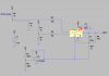
Attached you can find a picture showing my circuit. It is supposed to measure strain, using one strain gauge in the 3-wire configuration of the Wheatstone bridge. LTC2053 is used to amplify the signal by a gain of 96.3 (theoretically). The ADC is actually the integrated 12-bit ADC of a MSP430. Consider all resistors to have 1% accuracy. The intention is to measure strain levels up to 10000με.

What I want is to:
(1) Calculate the error of the electronics and thus find the accuracy that I can have when measuring the strain. Can you give me some guidelines please on how to do the calculation of the accuracy?
(2) Find ways to improve the accuracy. For example, if the resistors of the bridge are not perfectly matched, the bridge will not be balanced and this can lead to errors, which cannot be solved with calibration.

Software calibration is something that I can do, but I guess that some errors cannot be solved in this way, is that correct?

Nikos
 

Attachments

  • strain_gauges_AFE.PNG
    strain_gauges_AFE.PNG
    40.6 KB · Views: 388
Actually, you can zero out any bridge errors with a pot connected between R1 and R2. Reduce the value of R1 and R2 so the total of R1, R2 and the pot is 2k or as close to that as possible. If you need precision, include two calibrate switches. The first one swaps +3.3 and ground between the ends of R1 and R2. The leg is perfectly balanced when there is no change in output between the two switch positions. Use the other switch to do the same thing with R3 and R6 and a calibration pot at its common junction. Again adjust the pot for zero output at no load.

Now the only error will be in the form of nonlinearity in the sensor and thermal changes since the last calibration.
 
Hi Gary! Thanx for your reply!

Actually, you can zero out any bridge errors with a pot connected between R1 and R2.

Actually, this is something I knew but it is not easily applicable to my case. What I forgot to say previously is that the PCB is supposed to have very small thickness, thus I don't think that I can afford the thickness of a pot. Perhaps this can be done with a digital pot, but in that case I wouldn't have the proper hardware to program the pot's value.

Now the only error will be in the form of nonlinearity in the sensor and thermal changes since the last calibration.
Is there any way to calculate the non-linearity of the sensor, so that I know the error introduced by this in the final result?
And what about the errors imposed by the in-amp? Don't they have to be taken into account, too?
 
Last edited:
Actually, this is something I knew but it is not easily applicable to my case. What I forgot to say previously is that the PCB is supposed to have very small thickness, thus I don't think that I can afford the thickness of a pot. Perhaps this can be done with a digital pot, but in that case I wouldn't have the proper hardware to program the pot's value.
Use a 20 turn pot. The things are not much taller than a ½ watt resister and will give better calibration sensitivity.

Is there any way to calculate the non-linearity of the sensor, so that I know the error introduced by this in the final result?
And what about the errors imposed by the in-amp? Don't they have to be taken into account, too?
Yes, put a series of standard weights on the sensor and note the results. If you can’t orient the device to allow that, look at the manufacture’s data sheet. Last possibility, use a calibrated spring scale. I would think that this would only need to be done once at the time of construction. After that, just zeroing should be necessary as the environment changes and components age. Any nonlinearities should remain proportionally constant.
 
Status
Not open for further replies.

Latest threads

Back
Top