Continue to Site

Welcome to our site!

Electro Tech is an online community (with over 170,000 members) who enjoy talking about and building electronic circuits, projects and gadgets. To participate you need to register. Registration is free. Click here to register now.

  • Welcome to our site! Electro Tech is an online community (with over 170,000 members) who enjoy talking about and building electronic circuits, projects and gadgets. To participate you need to register. Registration is free. Click here to register now.

Equivalent Circuit

Status
Not open for further replies.

littleavent

New Member
Is there a device i.e, an IC, processor, etc. that would act like a 360 deg turn pot with multiple taps (4 or 8) that would vary from highest to low/no resistance between the taps 180 degs from each other. Need to be able to vary the speed of "rotation" and the speed of "ramping up" to max "rotation" and "ramping down" to minimum rotation. this is and audio application so noise limitation is critical. I've looked at electronic sequential switching as in light "chasing circuitry but there need to be a smooth transition between the loads (as in riding on a sine wave). Please review the attached jpeg. Thanks for any help/suggestions.
 

Attachments

  • new circuit.JPG
    new circuit.JPG
    46.7 KB · Views: 268
Unsure of understanding all of your explanation, but am familiar with optical rotary encoders, they can tell a microcontroller speed and direction of rotation to handle that in software to suit your needs. They have a transparency disc with etched grooves and optocouplers. My audio editor handles audio tracks speed and bidirectional positioning using that system with its 'transport' knob.
 
Thanks for the come back and please excuse my ineptness (and spelling). I am familiar with optical encoders, and syncro/servos and the like but what I am trying to find is some sort of "chip" that will accomplish what the schematic represents. An input (audio bandwidth) with multiple (8) outputs in sequence going form max to min, with the one at the "0" degree of a circle at maximum and the output at "180" degree at minimum. Imagine 8 outputs in circle in a "stopped" mode. Position (1) is at maximum or 100% (volume of 10), position 2 is at 75%max (volume of 7 1/2), position 3 is at 50%max (volume at 5), position 4 is at 25%max (volume of 2 1/2), position 5 is at 0% max ( volume of 0), position 6 is at 25%max (volume of 2 1/2), position 7 is at 50% max (volume of 5), position 8 is at 75% max (volume of 7 1/2). the circular array would be able (electronically) to go from no rpm to a set rpm (say 500 rpm) at a linear or non linear rate and back down to a set low rpm or stop. Again forgive my inability to describe what I have dreamed up here.
 
If you just want a varying volume control at each output, then you could perhaps use a series of digital potentiometers controlled by a microprocessor. You'd have to modify your circuit, since each potentiometer must be connected to the same ground point, but that would still give you your desired varying output at each tap.

The microprocessor would be programmed to vary the digital settings of each pot in sequence to give you the desired variation in volume. A digital control input to the microprocessor could vary the rate of the sequence.

Alternately you could likely control the pots with discrete logic, but that would appear to require a fairly complicated circuit.
 
Up down control

Here is a little block diagram to see if we are on the same page about what you are looking for. The way I understand it you have audio in and you want it to get louder and then softer and start over again. If thats it, see what you think of this type.
 

Attachments

  • encoder.GIF
    encoder.GIF
    26.4 KB · Views: 195
Appreciate the suggestion but I need to explain futher. Imagine a potentiometer/ reostat (I think a reostat is a better example) . These devices would not have an "stops' and would turn 360 degrees freely. The resistance would go from none to high as the "wiper" goes around the resistance media (carbon, wire wound.etc.) and back to the start of continuity. Now take (8) of these pots with one continuous shaft thru all of them. Each "body" of the pot would be indexed 45 degrees clockwise or couterclockwise (either direction but same direction on all of them) in sequence one below the other.
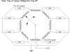
Lets think of them as volume controls into amps. there would be 8 volume controls, 8 amps, and 8 speakers. lets number the assemblies as 1,2,3,4,5,6,7,8. in a circle (clockwise or counter clockwise, doesn't matter). No.1 would be at max volume and no. 2 at 75% of max , no.3 at 50% of max, no.4 25% of max and no. 5 would be at 0% of max or minumum volume , no. 6 at 25% of max, no. 7 at 50% of max and no. 8 at 75% max when the shaft s NOT turning. As the shaft turns each speakers volume would rise and fall from minimum to maximum SMOOTHLY sequentially 45 degrees from each other causing an effect of sound going around in a circle. Think of a light chaser with 8 LEDs in a circle going around at variable speeds (but thats just switching). I am looking from some kind of solid state device that would do this electronically as opposed to a mechanical device which are availible (and expensive).
The digital pots have caught my interest and I will pursue futher. thanks for any input (now and in future). I will keep on with this project and will pass on what I find.
 
Hello again,


I think the digital pots is the way to go, or possibly 8 gain controlled amplifiers with an 8 phase ramp generator.
 
Fader Chaser

OK I think I got it. Here is the proposal:

1- Timer IC - sets the speed. (Adjustable)
2- Counter - Counts from 0 to seven then starts over.
3- Switches - These are logic switches controlled by the counter. (Counter 0 turns on all sw0's, counter 1 turns on all sw1's etc.
4- Resistor divider - Sets output from 0 to 100%

So the outputs will follow the chart.
The circuit would look like the schematic (only 4 outputs shown)
This should turn out to be less than 20 IC's and cost about $15 in parts not including a power source.
Did I get it this time?
 

Attachments

  • spkr1.PNG
    spkr1.PNG
    9 KB · Views: 162
  • spkr..GIF
    spkr..GIF
    30.5 KB · Views: 190
Hi,

I thought he said he wanted it to be continuously (or nearly so) variable and not stepped? Maybe you can make the steps small enough?
 
People can only perceive about a 3db difference so i think the one at 0 is the most important. The rest just kind of rotate. I'm guessing it is the location not the amplitude that creates the effect. But thinking about it an audio taper rather than a linear taper might be more effective.
 
Hello again,


Hey you know what we almost forgot to mention? PWM of course :)

The switches can be PWM'ed so that they can perform a nearly analog response with the audio. The switching frequency should probably be 200kHz or higher.
 
Thanks folks,
Sorry I haven't got back to you. (sigh, I need a patron so I could pursue these ideas full time, but I have to put bread on the table.
Some intriguing thoughts and comments. I will pursue and get back with results.
Let you know what I am doing, I am trying to create a "Leslie" type of speaker cabinet with NO moving parts. Emulators just will not do. Organs (especially the old Hammonds)
have to have these types of speaker cabinets to sound correct but they are huge, expensive, and can require a lot of maintenance. There, I've let the cat out of the bag. Please keep the comments and/or suggestions coming.
 
Status
Not open for further replies.

Latest threads

New Articles From Microcontroller Tips

Back
Top