Continue to Site

Welcome to our site!

Electro Tech is an online community (with over 170,000 members) who enjoy talking about and building electronic circuits, projects and gadgets. To participate you need to register. Registration is free. Click here to register now.

  • Welcome to our site! Electro Tech is an online community (with over 170,000 members) who enjoy talking about and building electronic circuits, projects and gadgets. To participate you need to register. Registration is free. Click here to register now.

EQ TILT unit schematic

Status
Not open for further replies.

MrDEB

Well-Known Member
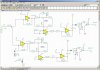
I think I have everything in order??
a stereo 5 band Tilt eq with 2 - 4x10 matrix displays
any suggestions are welcomed as I am an new with this audio stuff.
Inputs are from TV set, Ipod, stereo, radio
inputs are the mixer circuit posted earlier this week
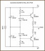
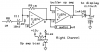
the filters are from application notes for the AND8177/D
display is from this circuit https://www.electro-tech-online.com/attachments/audio-spectrum-analyzer-en-pdf.15065/
and LOTS of valuable input from the good people on this site
 

Attachments

  • tilt inputs.pdf
    42.8 KB · Views: 354
  • tiltr filters.pdf
    62.4 KB · Views: 396
  • power supply.pdf
    30.3 KB · Views: 240
  • tiltr display.pdf
    65.8 KB · Views: 291
On the display, the 4017 Johnson counter appears to simply be a free running column driver. How does it sync to the row drivers? I also couldn't see where it connects to the LEDs?
 
The input opamps have a too low input impedance because the 1k resistors have a value that is for microphones, not for line level signals. The gain is the ratio of the 100k negative feedback resistance to the 1k input resistance which is 100 and is way too high. That is why you need such a high value for the input capacitor.
Replace the 1k resistors with 27k for a gain of 3.7 and replace the 10uF input capacitors with 0.33uF poly type.

The 1uf capacitor feeding the filters has a cutoff frequency of only 8Hz. If it is 0.47uF poly type then its cutoff frequency is a reasonable 17Hz. 0.33uF has a cutoff frequency of 24Hz.

Why are there transistors with diodes in the power supply circuit?
 
I also noticed a few problems here:
 

Attachments

  • EQ and display.PNG
    EQ and display.PNG
    8.4 KB · Views: 353
Power supply diodes and buffer

here is the source of the power supply and wondering about the input buffer that you suggested. using pin 12??
could be I misinterpted your suggestion or ?
need to take a second look at the 4017 circuit. orginally had two 4017's driving 2-10 x 10 displays.
 

Attachments

  • Rail_Splitter.gif
    Rail_Splitter.gif
    6 KB · Views: 430
  • sijosae2.png
    sijosae2.png
    4.7 KB · Views: 367
  • MrDEB's circuit.PNG.jpg
    MrDEB's circuit.PNG.jpg
    2 KB · Views: 720
I know this will go unanswered as I've asked it before. Why are you redesigning the circuit, you appear to have no idea how the parts even work or what they're for. Why not start with a more basic electronic circuit, flash an LED that sort of thing. It's a somewhat complex design for a beginner, are you going to layout a PCB or point to point hand wire it? If it's not carefully laid out it'll introduce noise into your audio. I know it's for a scout class but they'll all be adults by the time it's a prototype.
PS you don't need a rail splitter since you're using a dual rail supply. So nertz the transistors in the powersupply.
 
Not redesigning just compiling

Taking several circuits and combining into one unit.
If we build an EQ unit then great but the kid wants a display as well.
The display will introduce noise into the audio.
Taking a Tilt EQ circuit (see application notes AND8177/D) adding the display portion of the afore mentioned oriental circuit which resembles the Vellman circuit for the display.
Will get rid of the transistors and go with the two regulators.
Have reduced the displays from 2-10x10 units to 2- 5x10 units.
If we build unit in sections and get each section working it should be hopfuly easy to solve any problems.
And yes we are planning on home etching the pc boards.
Have already built a pocket Tilt unit w/ display(just need one more opa551 op amp to finish.
as far as redesigning I really don't feel like we are redesigning just combining.
thanks for the input
 
Mr. DEB,
Your circuit does not have a TILT control. It has a 5-band EQ circuit instead where the level of each band can be separately boosted or cut.

A TILT control boosts the highs and cuts the lows at the same time, or cuts the highs and boosts the lows at the same time, or is with a flat frequency response. Your circuit does not have it.
 
Since your going to build it in modules start with the power supply, it's the most basic schematic and yet can cause grief if you build it badly. Ground loops are puddle of fun in audio.
 
It looks like a TILT circuit.

looks like a Baxdall circuit as well.
I found this circuit on the application sheet for the AND8177?D (type in a search and its an ON semiconductor chip.
Plan is to build the power supply first
audioguru mentioned something about the op amp buffer. I searched for a buffer circuit and found the onepictured. The one in my circuit is to isolate the display noise from the audio.
I am still cntemplating the circuit using bi-lateral switches instead of transistors for multiplexing the frequency input to the lm3916 and using one peak detector?
will redesign it as per the Vellman circuit.
 

Attachments

  • buffer circuit.pdf
    19.2 KB · Views: 274
Each EQ frequency band needs to have its own peak detector. The multiplexing feeds the output of each peak detector to the LM3916 in sequence.

Your buffer opamp was upside down and backwards. It is supposed to have a high input impedance and a low output impedance like this follower opamp:
 

Attachments

  • buffer opamp again.PNG
    buffer opamp again.PNG
    12.2 KB · Views: 485
Really confussing filters

While looking for another filter circuit I ran across this one BUT the center frequencies are way different but the circuits are almost the same?
can't believe the 2.4K resistor changes the center frequency?
 

Attachments

  • Capture.jpg
    Capture.jpg
    340.1 KB · Views: 292
  • 10bandeq.gif
    10bandeq.gif
    9 KB · Views: 287
  • two same circuits.GIF
    two same circuits.GIF
    95.2 KB · Views: 324
The filters are for a one octave bandwidth. How are you going to decrease the Q so that each one covers two octaves?
 
will be 5 filters per channel

going to build 5 filters with different cap/ resistor combos.
hope thats what you are asking.
 
going to build 5 filters with different cap/ resistor combos.
hope thats what you are asking.
No, I am asking if you will modify the values in the filters so that they have a bandwidth of two octaves. Because the circuit has values selected for a total of 10 filters so that each filter has a bandwidth of only 1 octave. The Q of each filter must be reduced in order to increase their bandwidth.

I would give you the formula if I had it but I have never seen this filter before.
 
Status
Not open for further replies.

Latest threads

New Articles From Microcontroller Tips

Back
Top