Continue to Site

Welcome to our site!

Electro Tech is an online community (with over 170,000 members) who enjoy talking about and building electronic circuits, projects and gadgets. To participate you need to register. Registration is free. Click here to register now.

  • Welcome to our site! Electro Tech is an online community (with over 170,000 members) who enjoy talking about and building electronic circuits, projects and gadgets. To participate you need to register. Registration is free. Click here to register now.

EQ / spectrum analizer revisited

Status
Not open for further replies.
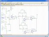
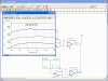
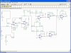
I removed U4 pins 8-9 and Vf5 now has some peaks!!
The schematic shows U4 pins 8-10 as an inverter. In TINA it is probably completely different, maybe it is the mixer.

If I remove U3 pins 5-7 won't the display circuit mix the filter outputs all together?
The schematic shows that the input of U3 pins 5-7 is from one filter. The filter drives only one the display driver, not all of them.
U3 pins 5-7 is shown driving only the input of inverter U4 pins 8-10. Both opamps are doing nothing.
The mixer is not shown on the schematic.
 
Only have part of mixer

here is a pic of TINA with the 47K resistors removed and all 4 mixer inputs included.
the outputs at Vf2 & 3 drive two seperate displays. have a total of 10 displays (5 right, 5 left).
Tina is showing two display driver outputs Vf2 & 3.
will simulate with filter pot at 10% and 90%
the 10K mixer input pot set at 50%
 

Attachments

  • 3-6-2009-9.47.49 AM.jpg
    3-6-2009-9.47.49 AM.jpg
    298.7 KB · Views: 162
pots set at 10% & 90%

screen shot one mixer input, filter pots at 10% and 90%
 

Attachments

  • 3-6-2009-9.58.05 AM.jpg
    3-6-2009-9.58.05 AM.jpg
    303.8 KB · Views: 159
  • 3-6-2009-9.59.25 AM.jpg
    3-6-2009-9.59.25 AM.jpg
    304.4 KB · Views: 150
filter pots at 50%

here is both pots at 50%
these shots are with out U4 pins 8-9, the 47K resistor is gone as well.
Maybe I am wrong but the U3 pins 5-7 are acting as a buffer to isolate the different frequencies to drive the displays??
 

Attachments

  • 3-6-2009-10.03.07 AM.jpg
    3-6-2009-10.03.07 AM.jpg
    303.5 KB · Views: 156
Your TINA simulation does not have decibels scales so it is almost meaningless.
The simulation shows a small amount of boost and cut.
the simulation shows no bass frequencies because the load resistors on the coupling capacitors have a value too low and act like highpass filters.

Your mixer is horrible:
 

Attachments

  • audio mixers.PNG
    audio mixers.PNG
    74.7 KB · Views: 151
Db scale is on the left side

I changed to your suggestion except I left the 10k pot in for adjusting input level.
Not to much difference when changing the pot - about 5-10db difference.
 

Attachments

  • 3-6-2009-7.26.01 PM.jpg
    3-6-2009-7.26.01 PM.jpg
    321 KB · Views: 162
here is an interesting looking wave form

using the signal analizer in Db magnitude
are these wave forms as interesting to you as they are to me.
I did 2 other filters with different results. one was for a guitar and the other had one sharp peak.
didn't look like it was doing as much. coarse in my circuit I have several outputs to displays.
 

Attachments

  • 3-6-2009-7.39.44 PM.jpg
    3-6-2009-7.39.44 PM.jpg
    318.6 KB · Views: 158
What are you doing?
The input opamp is inverting but it does not have an input resistor to set its gain. Then it is extremely noisy when the input pot is turned down.

If you do not want a mixer at the input (a mixer is an inverting opamp with an input resistor from each source) then the opamp should be non-inverting.

EDIT: Modified the input opamp.
 

Attachments

  • input opamp.PNG
    input opamp.PNG
    59.8 KB · Views: 148
Last edited:
I thought I had same as your post

with the mixer inputs (several 100k resistors connected to the inverting pin (-)
if connecting inputs to a stereo, radio, tv set etc do I want high or low impedence?
 
my bad

I connected to 100k resistor going from the input to the output on the wrong pin.
I took out the one resistor to groundchanged the cap to 470u as suggested.
after looking at the basic circuit I aded the last op amp just to see what it did.
the signal from vf5 takes a big dip but all the others I guess are still good?
 

Attachments

  • 3-6-2009-8.50.45 PM.jpg
    3-6-2009-8.50.45 PM.jpg
    331.9 KB · Views: 153
  • 3-5-2009-2.20.19 PM.jpg
    3-5-2009-2.20.19 PM.jpg
    167.1 KB · Views: 145
You messed up the input opamp so it is inoperative.
Vf5 is an extremely low signal voltage mixing node. Vf4 has the mixed output signal.

Can you turn off the dots that are all over the place?
 

Attachments

  • equalizer-spectrum analyser.PNG
    equalizer-spectrum analyser.PNG
    123.4 KB · Views: 235
I redid TINA using your mixer

I found an interesting artical talking about mixers
Simple Mixer Schematics
Just for the learning process I inserted drawing # 3
The outputs look exactly the same??
hard to read with the gray background. printed it out = readable
any comments on schematics?
 

Attachments

  • 3-7-2009-4.44.17 AM.jpg
    3-7-2009-4.44.17 AM.jpg
    327.2 KB · Views: 167
  • 3-7-2009-5.02.12 AM.jpg
    3-7-2009-5.02.12 AM.jpg
    327.5 KB · Views: 207
I thought you knew that an active mixer uses an inverting opamp and every input has its own input resistor.

But you do not show a mixer because yours has only one input. It is just an inverting opamp.
The second opamp is just an inverter and does nothing.

Can you turn off the dots that are all over the place?
 

Attachments

  • input opamp again.PNG
    input opamp again.PNG
    64.4 KB · Views: 168
only simulating one channel

I can't simulate more than one input.
the schematic is of one channel with one input.
I added some extra inputs in attached.
I show some screen shots of both inputs and one has 10db gain while the other shows -70 db loss
why I don;t know.
I printed out the explaniation of the circuit on
Simple Mixer Schematics
It's hard to read but down towards the bottom it says something about the circuit is a virtual ground and the summing of all the inputs.
interesting reading. weather its right??
like what do I know--not much in this field
 

Attachments

  • 3-7-2009-2.37.29 PM.jpg
    3-7-2009-2.37.29 PM.jpg
    326.9 KB · Views: 185
  • 3-7-2009-2.29.17 PM.jpg
    3-7-2009-2.29.17 PM.jpg
    333.3 KB · Views: 168
  • 3-7-2009-2.49.21 PM.jpg
    3-7-2009-2.49.21 PM.jpg
    326.9 KB · Views: 167
VF5 is a virtual ground without a signal voltage. It has some low and high frequencies because of the phase shifts of the filters and because C7 has some reactance that blocks some of the virtual ground effect.

The output is VF4 which shows two peaks at +10db.
Try simulating it with C7 replaced by a piece of wire.

OP3, OP6 and OP7 can be removed with no change in how the circuit works.
 
Last edited:
removed c7

inserted piece of wire = only VF5 changed
I want to keep op3 & 6 to act as a way to isolate the outputs of the filters instead of one output to the displays I have 5 per channel
I simulated without OP3 & 6 and all the peaks are then on the one output.
remember I have 5 peak detectors/displays per channel
As for op7- After reading the artical about summing all the different inputs (a total of 4 per channel)
not really sure if the following is gospel??
op7 as I understand from the artical, it reverses the phase/.
Because the summing node (The inverting input of the op-amp) is at virtually earth potential, there is little chance that this signal will bleed it's way out to any of the other inputs. Essentially speaking all the audio sources are isolated from each other.
However we're still left with the problem of the phase being wrong. If the output of the first op-amp were recombined with one of the other signals at a later stage it would cancel out rather than mix. So we have to re-invert the phase with yet another op-amp. This is a unity gain amplifier just like the first except that there is no summing node as such. (Except for the feedback resistor of course) The output of these two stages will now be the summ of all the inputs with the correct phase. Because of the inherent compensation of the feedback/op-amp/summing node, there is virtually no limit to the number of inputs you can put on this. Most modern op-amps have enough drive capability that 128 inputs would be just peanuts.
However it must be remembered that you are summing the inputs so if you had a powersupply of say +/- 15 volts, and 4 inputs of +5 volts each, The result would be 20 volts mathematically speaking. But the op-amp can only produce +15 volts so you would be clipping by 25%. Distortion occurs. Most op-amps can't swing exactly to the supply rails so clipping and distortion would be even worse. In practice however most audio signal wouldn't exceed a few hundred milivolts. A 2 volt peak to peak signal is considered to be a very high level.
 
inserted piece of wire = only VF5 changed
Yes only VF5 but were most frequencies at -75dB?

I want to keep op3 & 6 to act as a way to isolate the outputs of the filters instead of one output to the displays I have 5 per channel
I simulated without OP3 & 6 and all the peaks are then on the one output.
remember I have 5 peak detectors/displays per channel
The filter's opamp drives only its own peak detector. Adding the tiny loading of the output mixer makes no difference. OP3 and OP6 do nothing.
The output mixer is supposed to mix the frequencies together.

As for op7- After reading the artical about summing all the different inputs (a total of 4 per channel)
not really sure if the following is gospel??
op7 as I understand from the artical, it reverses the phase.
You cannot hear if the phase is reversed or not. Many opamps in your circuit reverse the phase and you cannot hear it. You are not mixing a non-inverted signal with an inverted signal like the article warns about.
 
leave the wire or capacitor??

it looks like it dosn't affect to output with or with out. just at vf5 point which I put there just to see what it has. not to be included in design
I want the displays to show what each filter seperatly is doing. without op3 & 6 all the signals are mixed together so all the displays will show the same.
as for the op7, I will take it out as it really isn't needed. I just inserted it as the artical showed it in the circuit.
 
took out op3 and 6

left the 100k resistors and I still get seperate waves for each filter.
Vf4 has all and vf2 & 3 have their own wave.dosn't look like I lost any Db gain. still at 10db
now to get back to the mixer input.
going to go back to your design = 1 op am, 1 pot and 1 resistor per input per channel
 

Attachments

  • 3-8-2009-7.10.46 AM.jpg
    3-8-2009-7.10.46 AM.jpg
    202.9 KB · Views: 165
it looks like it dosn't affect to output with or with out. just at vf5 point which I put there just to see what it has. not to be included in design
See how the VF5 now has a frequency response now that is the inverse of the open loop frequency response of the last opamp?
True, the design does not use VF5 as an output.

I want the displays to show what each filter seperatly is doing. without op3 & 6 all the signals are mixed together so all the displays will show the same.
The output of a filter feeds its own LM3915 display. It also feeds an input on the output mixer so that the audio of all frequencies are mixed together. Each display is separate from the other displays with or without OP3 and OP6. So remove OP3 and OP6.

as for the op7, I will take it out as it really isn't needed. I just inserted it as the artical showed it in the circuit.
Good.

EDIT:
It is very confusing talking about the opamps since their numbering is different on the schematic and on the simulation.
 
Last edited:
Status
Not open for further replies.

Latest threads

Back
Top