Continue to Site

Welcome to our site!

Electro Tech is an online community (with over 170,000 members) who enjoy talking about and building electronic circuits, projects and gadgets. To participate you need to register. Registration is free. Click here to register now.

  • Welcome to our site! Electro Tech is an online community (with over 170,000 members) who enjoy talking about and building electronic circuits, projects and gadgets. To participate you need to register. Registration is free. Click here to register now.

Emergency Stop Switch That Allows You To Disconnect Two Power Sources Once Enabled?

Status
Not open for further replies.

rs14smith

Member
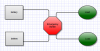
Does anyone know where I can find an emergency switch similar to the one below (design wise), that will allow me to disconnect two power sources if I press it?

The other alternative would be to have two separate emergency stop switches, and I would have to press both of them to disconnect power, however, I'm trying to simply things and have 1 switch that disconnect 2 sources. Refer to the image attached.

Emergency stop switch design example (I would prefer mine to be able to handle at least 25A)
**broken link removed**
 

Attachments

  • Screen shot 2011-06-05 at 8.09.52 PM.png
    Screen shot 2011-06-05 at 8.09.52 PM.png
    27 KB · Views: 385
Not really sure what you mean when you say you want to disconnect two power sources: do you mean two separate power sources connected to two separate loads?

In any case, you could use the classic "locked-out relay" circuit (described in this post). To disconnect n power sources, use an n pole relay (one with that many sets of contacts, one for each power source).

The beauty part of this circuit is that it is fail-safe, which is why it's used in industrial applications (you know, all those switch boxes with the big green and red buttons you see in factories and warehouses). When you reapply power, the circuit will be stone-cold dead until you hit the "start" button again.

Yes there are two separate power sources connected to two separate loads.

Could you possibly link me to an example of this LOR on an online store, as I only saw a schematic version in that post thread you linked to.

As mentioned, for both sources, I would simply need a switch that could handle 24v and 25A.
 
Heh; I don't think you can walk into Radio Shack and buy one.

Which is to say, it's something you have to builld (or get someone to build for you). Fortunately, it's really simple. I'll post a schematic for your specific app shortly.

What voltages are the power sources?

*********************************************************

This should work for your application:

**broken link removed**

The relay is any DPDT relay with the correct ratings. The coil voltage must be the same as at least one of your power sources (same voltage and DC or AC), and the contacts must be rated for your loads (25A, as you said).

The second source and load are completely isolated from the first source and load. Both will be disconnected together when the "off" ("stop") button is pressed.
 
Last edited:
Heh; I don't think you can walk into Radio Shack and buy one.

Which is to say, it's something you have to builld (or get someone to build for you). Fortunately, it's really simple. I'll post a schematic for your specific app shortly.

What voltages are the power sources?

*********************************************************

This should work for your application:

**broken link removed**

The relay is any DPDT relay with the correct ratings. The coil voltage must be the same as at least one of your power sources (same voltage and DC or AC), and the contacts must be rated for your loads (25A, as you said).

The second source and load are completely isolated from the first source and load. Both will be disconnected together when the "off" ("stop") button is pressed.

I'm trying to prevent from having to create one myself since something so common as to what I'm trying to do here should already exist such as this which appears to have this function but hard to tell: **broken link removed**

It has an A and a B side. I'll probably have to contact the seller, but creating one is my last option. Thanks for the schematic though, it may come in handy if I have to go down that road. Hopefully not :)

Here is another I found...again I think: https://cgi.ebay.com/Emergency-Stop...667?pt=LH_DefaultDomain_0&hash=item5639cf943b

Another: https://www.galco.com/scripts/cgiip.exe/wa/wcat/itemdtl.r?pnum=AVW422-R-IDEC
 
Last edited:
I'm trying to prevent from having to create one myself since something so common as to what I'm trying to do here should already exist such as this which appears to have this function but hard to tell: **broken link removed**

It has an A and a B side.

I don't know where you get that "A and B side" from; I don't see that. Plus it appears to be rated for only 10A.


That would work, but $27 for a switch? Give me a break. (Plus the current rating is unknown, and the seller is likely unable to provide it.)


Also only rated for 10A.
 
Last edited:
Does this by chance have anything to do with your DC motor project? You mention switching 25 amps but you don't mention if the 25 amps is AC or DC current? That is very important.

The switch you pictured in your original post is a pretty standard E STOP (Emergency STOP) switch with a large mushroom head on it. Switches like that are generally a multiple part switch. The head and button assembly being the "Operator" and then you have the "Contact(s) Block(s)". If you look closely at the image you can pretty much see how the parts snap together. E Stop versions generally use a N/C (Normally Closed) contact block or several contact blocks. Switches like this are generally configured into circuits like the typical start / stop design Carbonzit posted. All of this being well and fine but...............

You need to state the current (AC or DC) that will be switched as well as the voltage that will be switched. That is very important.

Ron

Sorry, yep it's DC and yep it's for the other project of mine, however, I'm jumping the gun regarding the volts, as I'm hoping after I test my project it will work well with just 24v and not have to worry about using the full 36v setup.

All in all, I'm looking for a simple way of doing this, however, if it proves to be difficult to find one suited for my needs, I can revert back to plan B and use 2 individual E stop switches.
 
I'm hoping you'll at least consider my suggestion (the locked-out relay). Very easy to wire up; no current requirement for the switches, as the load current is handled by the relay. Only possible drawback is that it requires a "start" switch as well as a "stop" switch.
 
I'm hoping you'll at least consider my suggestion (the locked-out relay). Very easy to wire up; no current requirement for the switches, as the load current is handled by the relay. Only possible drawback is that it requires a "start" switch as well as a "stop" switch.

Well I assume after looking at your schematic my opening post was not clear or detailed enough, as my main point was, I would like a basic system that only includes 1 switch (E stop switch), and when that switch is pressed, it disconnects power to "both" circuits. When you manual lift that switch/button back up to it's original position, it unbreaks to the two circuits. It's like combining 2 E-stop switches into 1 which is a simpler overall system.

It's hard to see why something this basic isn't widely used, but that's what I'm after if there is one out there that can handle more than 10A, as that's mostly what I've ran into.
 
You could always use one of those big red switches connected to a relay; that would give you the 1-button operation you want and the current-handling capacity. (Again, relay coil must match supply voltage.)
 
You could always use one of those big red switches connected to a relay; that would give you the 1-button operation you want and the current-handling capacity. (Again, relay coil must match supply voltage.)

I wish there was a website that sold nothing but relays or E-stop buttons! lol I don't even know what the correct term is for that switch (big red button) you just refereed too is called.

I worked with small relays last semester in my IC class, however, we just did basic stuff and made sure we understood the logic behind it, but now when I really need to use a relay in the real world, it's becoming a pain in butt.

I'll try to find this big red button relay, but I still don't see how that will control two individual circuits?
 
Sorry, yep it's DC and yep it's for the other project of mine, however, I'm jumping the gun regarding the volts, as I'm hoping after I test my project it will work well with just 24v and not have to worry about using the full 36v setup.

All in all, I'm looking for a simple way of doing this, however, if it proves to be difficult to find one suited for my needs, I can revert back to plan B and use 2 individual E stop switches.

Why did I suspect this was motor project related? :)

There is a learning curve at work here. Sometimes when we seek simple, things get complicated. Something as simple as a switch gets complicated.

Here is a little of what you are looking at. If you simply want to switch a few amps, no big deal. However, when you want to switch a bunch of amps on and off things get complicated. As if the bunch of amps (like 25 or so) isn't bad enough then someone mentions that switching AC and DC current are two different animals to toss a wrench in the works. This does not even get into if the load is inductive or resistive in nature as switches (and relays and contactors) really care about that too. Your motor is an inductive load with DC current.

The E Stop switches you linked to are designed for use in circuits just like those Carbonzit has posted. If you would like more variations I can toss in a few more. The results will be the same. There are ways to switch high current and a simple switch with simple On/Off contacts is not the way it is done.

In your other thread you mentioned a big spark. Go ahead, take your batteries, get 24 VDC and just touch two wires together to start your motor. Even with the motor unloaded big spark huh? Really bigger when you disconnect the two wires. Good reason for that but think about something. That same spark will happen on the switch, relay or contactor contacts every time the motor is turned on or off. The poor contacts must take a heck of a beating huh? Starting to get the picture?

If you want an inexpensive means to switch high DC current then look towards automotive relays designed for switching high DC current. Also, read what I wrote about how E Stop switches are designed. They can have multiple contact poles, I mentioned how they were assembled.

I'll try to find this big red button relay, but I still don't see how that will control two individual circuits?

Would you like a circuit?

Ron
 
Last edited:
You are as I recall using 3 batteries. I will make you a simple circuit using a start and stop (the stop can be your E Stop or any normally closed push button switch). We will do it based on 12 VDC for the control portion in an effort to make things cheap. Just make sure you go back and read as well as reread what has been posted. The idea here is for you to understand what the hell is going on with the circuit as in how it works. If not this evening I'll have something in the morning.

Ron
 
Attached is a version of what has been posted. It is generic because lacking motor data (exact motor data) it is difficult. RY1 is a standard automotive relay, RY2 would be slaved to RY1 and that is a high current relay (contactor) capable of the max current of both motors.

Ron
 

Attachments

  • Motor Start Stop.gif
    Motor Start Stop.gif
    16.3 KB · Views: 490
I'm kinda dissapointed. I'm sure my three phase contacter would work but no one commented.
Maybe the request for an "off the shelf" version fell on deaf ears.

Mike.
 
Status
Not open for further replies.

Latest threads

Back
Top