Continue to Site

Welcome to our site!

Electro Tech is an online community (with over 170,000 members) who enjoy talking about and building electronic circuits, projects and gadgets. To participate you need to register. Registration is free. Click here to register now.

  • Welcome to our site! Electro Tech is an online community (with over 170,000 members) who enjoy talking about and building electronic circuits, projects and gadgets. To participate you need to register. Registration is free. Click here to register now.

Electro Mechanical Clock Chime

Status
Not open for further replies.
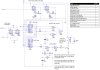
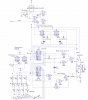
Corrected diagram enclosed.
I have added the missing diode. The slow release will be good as it will tend to remove any release noise (audio)from the relay as the bell is sounding.

I prefer your idea of using 4013s and have ammended the diagram.

I have added a note about unsued I/P pins on the logic gates but will add them into the fianl diagram when I know what is left unused from this and the digital clock cct.

I think when I used Orcad around 10 years ago it used to do this for you.

Brett.
 

Attachments

  • chimev2.jpg
    chimev2.jpg
    67.1 KB · Views: 661
I have not checked all of the IC pin numbers, but otherwise I can't see any errors.

You could use a MOS FET such as the 2N7000 for Q1 in lieu of the bipolar.
You should retain the 1k as FETs usually need a gate "stopper".
 
I have been playing around with a sub miniture relay and have managed to get it to ring a bell. All I did was solder a small metal strip to the armature with a blob of solder at the end of the strip as the hammer.

I have a larger relay on order as it does need a bit more power. All I need now is a bell with a nice ring to it.

I have also drawn up a rough vero layout for the componets.
 

Attachments

  • chimevero.jpg
    chimevero.jpg
    47.5 KB · Views: 587
oliverb said:
I have been playing around with a sub miniture relay and have managed to get it to ring a bell. All I did was solder a small metal strip to the armature with a blob of solder at the end of the strip as the hammer.

I have a larger relay on order as it does need a bit more power. All I need now is a bell with a nice ring to it.

I have also drawn up a rough vero layout for the componets.

You may be able to buy a solenoid with a moving rod through the centre as suggested in your circuit.

As for the layout, if you rotated either IC1 or IC 2 through 180 degrees, it would make 2 of the connections shorter, eg. rotate IC2, then IC1/14 to IC2/13 and IC1/11 to IC2/12 would be short.
 
ljcox wrote:
You may be able to buy a solenoid with a moving rod through the centre as suggested in your circuit.

I have tried a solenoid as per my cct but it is tricky to get a "soft" sound. You do not want the hammer to strike the bell directly but to stop short and strike the bell by using the flex in the hammer shaft. I could make the solenoid strike a remote hammer shaft fixed to a pivot and fix in an adjustable stop.

Relay armatures stop against the coil and have a built in pivot at their ends with the contacts acting as a return spring. As long as you can fix a hammer and flexable shaft to the armature they seem quite simple to get working.

In the end both will work it just depends on what materials you have to hand.


ljcox wrote:


As for the layout, if you rotated either IC1 or IC 2 through 180 degrees, it would make 2 of the connections shorter

I did look at this due to the number of connections between IC1 and 2 but decided to keep all the ICs aligned to avoid errors when wiring. This is especially true when wiring the back of the board where you can't see the IC sockets.
I tend to position the ICs next to each other depending on the amount of interconects.

Brett.
 
I do the wiring on the component side.

Have you considered an electonic bell sound. eg. I downloaded the Big Ben chimes. I expect you would have to extract one "dong" from the file and load it into a ROM and have a counter to run through the ROM for each dong.

Have you considered using an old door bell? Either the mechanical type that has solenoid (I did read what you said) or an electronic one.
 
I tend to do all the short runs including the Batt and Earths on the solder side where you have access to all the copper under the ICs and the longer runs including to other boards, displays and switches etc on the conponent side.
On Tripad board you only get access to 1 hole on the conponent side.


I did consider using parts from a doorbell but they are too big. The solenoid/relays I have been using are less than 25mm square.

I really want to stay away from electronic sounds as they don't sound the same. I have ruled out rods and spiral gongs as in my Westminster Chiming clocks as they are far too loud. I like the soft "ding" you get from many grandfarther clocks.
Brett.
 
A trick that I use when there are not enough holes for the wires is to drill out the hole to 1 mm and insert two 0.4 mm wires.

Have you ever opened up an old phone that has real bell gongs inside?

I used to be a telephone technician in a previous life. The ringing signal is an AC voltage that causes the gong hammer to alternate back and forth between the gongs. The gongs have a hole that is drilled off centre so each can be adjusted so that there is a small gap between the hammer and the gong.

If you can find such a phone, it may be just what you need. However, note that there is a permanent magnet in the magnetic circuit to act as a bias. You would have to remove this and install a return spring (or possibly mount the unit horizontally so gravity will do the job.

You don't necessarily have to use the phone gongs, only the hammer and coils.
 
ljcox wrote:
Have you ever opened up an old phone that has real bell gongs inside?

I have opened a few. I worked for BT as an Exchange engineer for about 20 years. The 1st 10 years on the old Strowger Exchanges.

As part of my 1st year as an apprentice we had to study customer apps. This meant learning all the circuits in the old teles, plan 107s etc off by heart.

Although the bell drive itself may be too big the bells could be just what I am after.

I have had a word with a friend at work who collects old phones and he is going to bring me in a selection of different bells and thier mounting to try out.
Thanks.
Brett.
 
Update

I have just completed the Chime Cct and can confirm it all seems to work.

In the end I did not use the adjustable pulse generator but used the 1Hz pulse from the clock to drive the chime. I found this to be just right it also looks good as the chime is in sync with the seconds display.

I have added a chime on/off switch and an LED to indicate when the chime is off.

I will also add 4 LEDs to IC2 binary output so I can see what the chime cct is set to. This is handy when you want to sync the time to the chime.
I could have used a 7 segment display and decoder here but it is a lot of extra wiring when 4 LEDs wil work fine.

I have used a bell from an old telephone and have used a relay with a length of 2.5mm copper wire soldered to the armature as the hammer.

This give the nice soft chime I was looking for.

I will post the final diagrams and pics when I get a sec (I have a bit of lacing up and letraset work on the display to complete the clock).

Again a big thank you to ljcox for all his help with this project.

Brett.
 
If you have some space inside the clock, mount an audio resonant cavity near the bell.

For years, the doorbell for my house was two metal bars which were struck by a solenoid's hammer. It wasn't vey loud and instead of "ding dong", it sounded sort of like "clank clank".

I bought a replacement cheap Chinese doorbell that has two plastic resonant cavities below the vibrating bars. What a big difference and improvement! It sounds like a much bigger and louder real chime. :lol:
 
The main problem with the chime is hiding the sound of the relay operating and releasing. I am going to mount the relay on rubber pads and add some rubber to the back of the armature to isolate it from the bell.
Brett.
 
Here is the final diagram and picture of the front of the clock.

I have added a switch to turn off the chime. There is an LED to indicate when the chime is off.

LEDs are now connected to IC2 binary O/P so the chime can be set without waiting for the clock to chime out.

Brett.
 

Attachments

  • chimev3.jpg
    chimev3.jpg
    79.9 KB · Views: 550
  • masterclock_196.jpg
    masterclock_196.jpg
    26.5 KB · Views: 472
oliverb said:
The main problem with the chime is hiding the sound of the relay operating and releasing. I am going to mount the relay on rubber pads and add some rubber to the back of the armature to isolate it from the bell.
Brett.
Did you consider using a 2000 type relay from an electromechanical exchange? Or an Ericsson relay from a crossbar exchange? The Ericsson relays have a plastic shim between the armature and coil face rather than the metal stud in the 2000 type. So the Ericsson ones should be less noisy.

Its a pity that you could not have accessed the binary bits from the hours counters in the main clock. Then the sync would be automatic. I thought of decoding the 7 segment lines to convert back to binary, but it seemed rather messy.

I glad to be of assistance.
 
ljcox wrote
Did you consider using a 2000 type relay from an electromechanical exchange? Or an Ericsson relay from a crossbar exchange? The Ericsson relays have a plastic shim between the armature and coil face rather than the metal stud in the 2000 type. So the Ericsson ones should be less noisy.

I did think about using a 2000 type relay. In some ways they are ideal as they have plenty of power and have a large armature with plenty of travel.
I still have all my old tools for maintaining and adjusting them including a huge armature adjusting tool and gram guages etc.

The main problem with these relays is that they are 50volt (I do run them off 25volts) and they are huge. The relay I am using is only 15x20x15mm smaller than a 2000 type relay armature.


The manual sync of the chime is fine. All I have to do is tap away at the Chime sync switch untill the Chime LEDs indicate the hours in binary let the clock chime out and it is set. Somehow it just fits in fine with the electro-mechanical feel of the clock.

Brett.
 
Some 2000 type relays don't need 50V. eg. the A impulse reception relay.

I know the armature bender you mentioned. But don't have (or need) one. I prefer the Ericsson relays.
 
Clock Chime update

This circuit has been up and running for over a year now and I have now changed the chime bell to a larger unit driven by a 30sec slave clock motor. See below for pic. More details on the master clock link below.

I have made a short clip of the chime in action with sound here

**broken link removed**

Also check out My master clock thread here

https://www.electro-tech-online.com...lock-with-7-seg-led-displays-hourly-ch.18901/

and Driving quartz clock motors here

https://www.electro-tech-online.com/threads/driving-quartz-clock-motors.25025/

as all these threads are linked.

Brett.
 

Attachments

  • chime.jpg
    chime.jpg
    32.8 KB · Views: 321
Status
Not open for further replies.

Latest threads

New Articles From Microcontroller Tips

Back
Top