Continue to Site

Welcome to our site!

Electro Tech is an online community (with over 170,000 members) who enjoy talking about and building electronic circuits, projects and gadgets. To participate you need to register. Registration is free. Click here to register now.

  • Welcome to our site! Electro Tech is an online community (with over 170,000 members) who enjoy talking about and building electronic circuits, projects and gadgets. To participate you need to register. Registration is free. Click here to register now.

Electro Mechanical Clock Chime

Status
Not open for further replies.

oliverb

Member
I have built a digital clock seehttps://www.electro-tech-online.com/threads/walters-or-no-walters.19324/
and want to design a cct to chime the hours using an old Grandfather clock bell. I plan to use a solenoid or hammer attached to a relay armature to strike the bell.

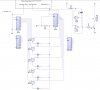
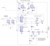
I have come up with the cct below but have got stuck. I need a cct to stop pulsing when IC1 is reset (pin0 logic1) but to start pulsing when an hourly pulse is received.

I have 1 second and faster pulses available from the clock or some sort of timer or astable could be used to drive the chime pulse as long as it is stopped and started as above.

The cct should work as folows every hour IC2 steps on 1 driven by the hour pulse. The hour pulse starts the Chime Pulse and continues to chime untill the O/P pins of IC1 matches the count of IC2 when it is reset via the relevant 12 AND gates. This in turn stops the Chime pulse.

IC1 and 2 would be linked to 2nd counters to enable the chime to count 12 then the hourly count would be reset.

Can anyone spot an easy solution or is there a better cct in existance already?

PS. I have never used PICs but would like to start using them so a solution using PICs is not out of the question. It could be a good excuse to go out and buy a book & programmer.

Thanks in advance.
Brett.
 

Attachments

  • chime.jpg
    chime.jpg
    44.5 KB · Views: 1,548
Consider a microcontroller solution, like the PIC, Texas MSP430 or the Atmel 8051 flavors or some other.
The HW is much simplified with even the cheapest MCU.

Also the digital clock on your other post could have been done with only a fraction of the components if you used a microcontroller. There are built-in programmable timer(s) in MCU's and it is easy to make a 1 second interrupt base by subdividing the 32768Hz clock with a timer. (Here speaking about Texas MSP430, the only MCU I know good). Then any other event handling (like 30 seconds or 1 hour) is just a matter of SW.
 
You could use a PIC, but there is a learning curve.

Rather than use 4017 counters, it would be better to use presettable binary counters.

I'll draw a circuit for you and post it later.
 
Here is the basic idea. In order to finish it, I need to know more about the digital clock.

1. Can you access the Hour digit in binary? If so, IC2 is not required, if not,

2. Can it output a pulse at 1 o'clock? If not, can it output one at 12 o'clock?

3. If the answer to all of these questions is no, how do you propose to keep IC2 in sync with the digital clock? It could occasionally slip.

4. Can you obtain a 1 Hz signal from the digital clock?

Forget these questions, I just noticed you posted a link to the digital clock circuit. I'll modify the circuit to suit and post later

Circuit description (I suggest you download the data sheet for the 4516 counter)

IC1 is configured to count down, IC2 to count up. They increment/decrement at the positive edge of the pulse input to C.

When PE is high, the counter is set according to the state of inputs P1 to P4. So when IC2 reaches 13 (as detected by the gating labelled a - I'll draw the detail when & if necessary), it is rapidly preset to 1.

After chiming, IC1 is held at 0 since Co is low - edit, there is an error in the circuit here, I'll fix it after your response.

The "start chime" signal is generated from the 1 Hour pulse by a differentiation circuit not shown. This presets IC1 to the current time (IC2 holds the current hour). Thus Co goes High and so IC1 decrements after each chime pulse.

The Schmitt Trigger NAND gate (b) generates short pulses (as set by R1 & C3) to set the length of the chime pulse.

Gate c is a NOR gate (performing the AND function) that allows the 1 Hz pulses to reach the transistor while Co is High.
For example, at say 2 o'clock, IC1 is set to 2 and decrements after the first chime pulse (ie. at the positive edge of the signal from b).

After the second chime pulse, it decrements to 0, so Co goes low thus closing gate c and preventing further chiming.

Edit, see next post
 

Attachments

  • chiming_circuit.gif
    chiming_circuit.gif
    44.1 KB · Views: 1,350
Here is the revised version. IC3 is a 4093 Quad Schmitt NAND and IC4 is a 4025 Tripple 3 input NOR.

The monostable is necessary since the 1 Hour pulse will be fairly short and thus must be extended.

The inverters can be made from unused gates.

I can't see any easy way to ensure synchronism between the digital clock and IC1. However, if you wish to explore this, I have some suggestions.
 

Attachments

  • chiming_circuit_130.gif
    chiming_circuit_130.gif
    28.8 KB · Views: 1,413
Wow thanks ljcox.

Your cct looks good and best of all uses far fewer componets than my design.

I'm going to print it out and have a good look through it at lunch time today.

I have a quick question. There are monstables built into the digital clock pulse circuit IC8c&d etc can I use this instead of the dual monostable in your design?

As far as synchronisation all I was going to do was have a manual input from a switch to step up IC1 in this case. There is a 24 hour pulse from the clock I suppose I could use this to do a reset at midnight perhaps using a long delay of around 15seconds to allow the clock to chime out 12 times. That reminds me I must add a chime disable button!

Thanks again.

Brett.
 
Yes, if the are monostables in the clock, then use them.

I thought about using the 24 hour pulse to reset IC2 after the chiming has finished as you wrote.

You don't necessarily need a timer to make it wait until the chiming is finished since IC1/Co goes low at the end of the chiming sequence. This signal could be used to trigger the reset. But you would need something to remember that the 24 Hour pulse has been received, eg. a Flip Flop.

I also thought about using the 30 second sync signal to provide the delay, but I could not work out how it works. It appears that it occurs when the Sec Tens count reaches 6, not 3. Perhaps you can enlighten me.
 
The 30 second pulse is taken from IC 1 & 2 a couple of 4017. These were in the cct as I had planned on using a 32768MHz crystal not 32.768KHz.

The 30 secs is synchronised with the display by operating the 30 sec Sync switch until the seconds hit 60. It seems to work really well and only needs doing once on initial power up.

I had planned on using the 30 digits but then realised this only happens every 60 seconds. I suppose I could have used the 30 and 60 seconds pulse together.

Anyway this does at least mean there are other pulses available from the 4017s.

I hope to test your cct out tonight using Livewire I'll let you know how I get on.
Brett.
 
Can you clarify a couple of things in you diagram?
I have IC4a as a 4025 so is IC4b a 4025 as well?
Also the componets shown as triangles with the not symbol are these standard inverters eg 4069 ?

Brett.
 
oliverb said:
Can you clarify a couple of things in you diagram?
I have IC4a as a 4025 so is IC4b a 4025 as well? Yes, the usual convention is the designate parts of an IC as a, b, c, etc. In the case of IC4b, connect 2 inputs together to form a 2 input gate. However, see the second suggestion below
Also the componets shown as triangles with the not symbol are these standard inverters eg 4069 ? They are inverters, but they can be unused parts of the NAND and NOR gates as in your digital clock circuit, eg. IC2b (under the Min Tens 7 segment display) You can use the 4069 if you wish, but it won't be necessary if there are enough spare gates

Brett.

I have posted 2 suggestions.
1. a method to reset IC2 at midnight.
2. a chime pulse generator.

I feel that a 1 Hz chime pulse rate will be too fast. This one allows you to set the rate and pulse length by selection of R1 and R2. I have shown approx values to give you a starting point. Note that the CMOS Schmitt Triggers have wide spreads and so you will have to either "select on test" or insert pots. You may also have to change the capacitor value, but it will vary both pulse length and rate. The other advantage is that this configuration requires one less inverter.
 

Attachments

  • chime.gif
    chime.gif
    47.1 KB · Views: 1,352
Oops, there is an error in the gating shown previously.

I have also added protection against the possibility of a decoding spike.
 

Attachments

  • chime_correct.gif
    chime_correct.gif
    3.1 KB · Views: 1,098
I am unable to test the cct on Livewire as it does not like logic gates teed off IC feeds. It did not work on the logic gates between my clock display and 7 seg decoder chips either but they work fine.

I will go ahead and build it on breadboard.

I will only be able to know the correct chime rate when the cct is running (by ear) so your idea of adjustable pulse length and rate will be perfect for this.

Thanks again.
Brett.
 
oliverb said:
I am unable to test the cct on Livewire as it does not like logic gates teed off IC feeds. It did not work on the logic gates between my clock display and 7 seg decoder chips either but they work fine.

I will go ahead and build it on breadboard.

I will only be able to know the correct chime rate when the cct is running (by ear) so your idea of adjustable pulse length and rate will be perfect for this.

Thanks again.
Brett.
I don't know what "livewire" is. I assume it is a simulation programme. I never bother to simulate, I do that on paper.

PS did you see the previous post? You were doing your's while I was posting it
 
Yes I did miss your post and I also missed it on the diagram as well. When checking the cct I think I read Q1 to Q4 on your diagram in reverse as my print out is very faint.

I will ammend it my Livewire drawing.

Livewire is a simulate program and has lots of errors but is fantastic for learning how basic ccts work and of course for cct drawing.

Brett.
 
Is livewire free? If so, where did you find it?

It may be useful to me for drawing circuits. I use Powerpoint (or for rough ones, I use the scanner + Powerpoint). This is not ideal as Powerpoint is not specifically designed for drawing circuits.

I suggest you draw the circuit and post it so we both have a consolidated drawing to work from.
 
Here is a paper I wrote some years ago that may be of interest.
 

Attachments

  • gating_115.gif
    gating_115.gif
    7.8 KB · Views: 768
Livewire is not free but is only around £30 in the UK and very good value for money. If jou just want to draw ccts diagrams then I would not reccomend it as it is very basic.

For veroboard layout I use Lochmaster again about £30 from the web.

There are some free programs about if you do a search on this Forum.

I will post the diagram poss tonight. Livewire has no monostables and I can't seem to buy then anyway so I will draw then from logic gates.


Brett.
 
If you can't buy a dual monostable, then you could use a 556 (dual 555)

This can be configured as a monostable.
 
Chime CCT awaiting a few queries.
I have a couple of queries the NOT Q output on your 1st monostable can this be replaced with a NOT Gate from Pin 5 of IC7a on my diagram?

Also the gate before the resistor on the transistor is this a not gate with active low IP?

Will repost diagram with corrections later.


Brett.
 

Attachments

  • chimev1.jpg
    chimev1.jpg
    56.6 KB · Views: 696
oliverb said:
Chime CCT awaiting a few queries.
I have a couple of queries the NOT Q output on your 1st monostable can this be replaced with a NOT Gate from Pin 5 of IC7a on my diagram? No, the 556 needs a short negative going pulse to trigger (see the marked up circut). However, see my alternative suggestion.

Also the gate before the resistor on the transistor is this a not gate with active low IP? Quite right, ideally the inverter should have an active high output.

Will repost diagram with corrections later.

Brett.

I forgot to transpose the IC1 & IC2 designations (in order to coincide with your's) in the chime p attachment.

I noticed that there is no diode across SL1.

Note that, the diode will slow the release of SL1. If you find that this is undesirable, you can insert a resistor in series with the diode to speed it up. If you wish to do this, tell me the resistance of SL1 and the type of transistor you intend to use and I'll calculate the resistor value for you.
 

Attachments

  • chime_fix.gif
    chime_fix.gif
    49.4 KB · Views: 700
  • chime_p.gif
    chime_p.gif
    37 KB · Views: 720
Status
Not open for further replies.

Latest threads

New Articles From Microcontroller Tips

Back
Top