With out commenting on "the circuit"; The question is "reason why?". "Explain".
The point of the circuit is to take DC and make AC.
Solar power is DC. Direct Current. Like a car battery.
"Grid" power, like from a wall out let is AC. Alternating Current. It switches + and -, 60 or 50 time a second.
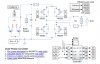
The parts "MOS1....MOS4" are like switches. Then can be on or off.
The point of the circuit is to take DC and make AC.
For a short time MOS1 and MOS4 are on while 2 & 3 are off. This connects the (+) side of the power (see red lines).
For a different short time MOS2 & MOS3 are on and connect (-) to the power line (see blue lines).
Another way to say it. Put the battery across the power line for a short time, remove the battery, turn it arround, put it back across the power line. (DC is switched around to make AC)
View attachment 117148
I hope this helps. Very simple answer. It is a little more complicated that the simple answer.
Please ask more questions.